Initialization by Wizard
After the deployment succeeds, open Chrome 66 or later and navigate to http://management_node_ip:5000 to access the ZStack Cube Ultimate UI. For the first login, you can use the default account admin and the initial password password.
- Automated Initialization: The system scans hardware automatically and creates/adds basic resources on the platform.
- Manual Initialization: Manually creates/adds basic resources on the platform.
This tutorial focuses on the automated initialization process.
 Note:
Note:
- If you exist the Wizard page or delete key resources during initial setup, you are not directed to the wizard again.
- We recommend using wizard to complete the basic platform configuration.
Automated Initialization
Automated Initialization
- Zone: A zone is a logical group of resources such as clusters, L2 networks, and primary storage. Zone is the largest resource scope defined in the Cloud.
- Cluster: A cluster is a logical group of hosts (compute nodes).
- Host: A host provides compute, network, and storage resources for VM instances.
- Backup Storage: An image storage is a storage server that stores VM image templates, including ISO image files.
- Primary Storage: A primary storage is one or more servers that store volume files of VM instances. These files include root volume snapshots, data volume snapshots, image caches, root volumes, and data volumes.
- Instance Offering: An instance offering defines the number of vCPU cores, memory size, network bandwidth, and other configuration settings of VM instances.
- Image: An image is a template file used to create a VM instance or volume. Images are categorized into system images and volume images.
- L2 Network: An L2 network is a layer 2 broadcast domain used for layer 2 isolation. Generally, L2 networks are identified by names of devices on the physical network.
- L3 Network: An L3 network includes IP ranges, gateway, DNS, and other network configurations that are used by VM instances.
Note: If you do not configure a business network when deploying ZStack Cube Ultimate, the system does not automatically create L2 and L3
networks during the automated initialization and you need to manually create them.
For more information, see Create Network- The system creates hosts, backup storage, and primary storage according to the hardware information it scans.
- The system creates multiple instance offerings:
- Balanced Type: The CPU-to-memory ratio is 1:4, such as 1C4G, 2C8G, 4C16G, and 8C32G.
- Compute-Enhanced Type: The CPU-to-memory ratio is 1:2, such as1C2G, 2C4G, 4C8G, and 8C16G.
- Memory-Enhanced Type: The CPU-to-memory ratio is 1:8,such as 2C16G, 4C32G, 8C64G, 16C128G.
- The system creates multiple disk offerings, including 20GB, 40GB, 100GB, 200GB, and 500GB.
Note: If any resources fail to be created or added, click Retry
to reattempt the failed step and continue initialization.Create Network
If you do not configure a business network when deploying ZStack Cube Ultimate, the system does not automatically create L2 and L3 networks during the automated initialization and you need to manually create them.
Create L2 Network
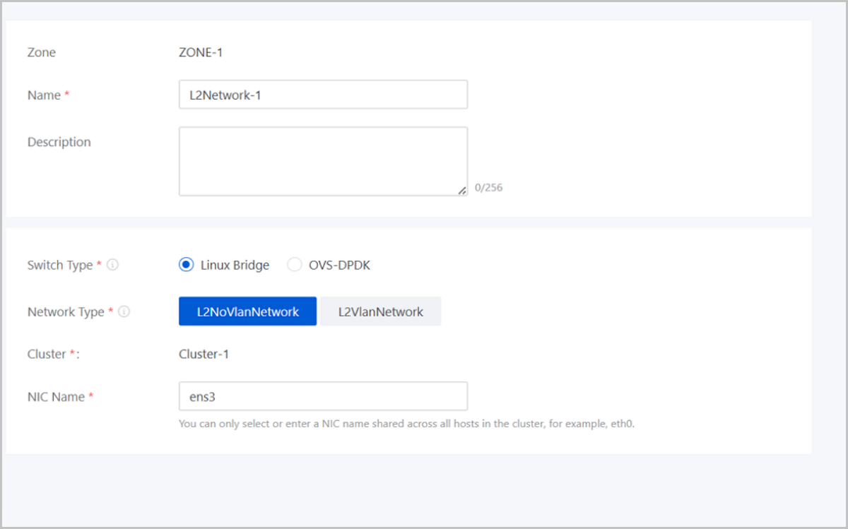
- Name: Enter a name for the L2 network.
- Description: Optional. Enter a description for the L2 network.
- Switch Type: Supported switch types include Linux Bridge and OVS-DPDK.
- Network Type: Choose a network type for the L2
network. Valid values: L2NoVlanNetwork, L2VlanNetwork.
- L2NoVlanNetwork
- If you do not need to use VLAN, select L2NoVlanNetwork.
- If you select L2NoVlanNetwork, the switch port connected by the specified NIC must be in the Access mode.
- L2VlanNetwork
- If you need to use VLAN on ZStack Cube Ultimate, select L2VlanNetwork.
- If you select L2VlanNetwork, the switch port connected by the specified NIC must be in the Trunk mode.
- VLAN ID: Enter a VLAN ID that matches the actual network configurations. Valid values: 1 to 4094.
- L2NoVlanNetwork
- Cluster: Display the the cluster to which the L2 network will be attached.
- NIC Name: Select or enter an NIC
name for the L2 network. For example, em01.Note: You can only select or
enter an NIC name shared across all hosts in the cluster.
Create L3 Network
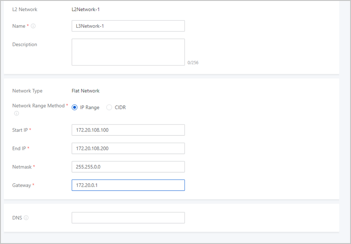
- Name: Enter a name for the L3 network.
- Description: Optional. Enter a description for the L3 network.
- Network Type: The wizard supports only flat network.
- Network Range Method: Select a method to add a
network range for the L3 network. You can select IP Range or CIDR.If you select IP Range, you need to set the following parameters:
- Start IP: Set a start IP address for the network range, for example, 172.20.108.100.
- End IP: Set an end IP address for the network range, for example, 172.20.108.200.
- Netmask: Set a netmask for the network range, for example, 255.255.0.0.
- Gateway: Set a gateway for the network range, for example, 172.20.0.1.
- DNS: Add a DNS server to provide domain name resolution services for the L3 network. You can specify 223.5.5.5, 8.8.8.8, or 114.114.114.114.
If you select CIDR, you need to set the following parameters:- CIDR: Set a CIDR block for the L3 network, for example, 192.168.108.1/24.
- Gateway: Set a gateway for the L3
network, for example, 192.168.108.1.Note:
- You can use the first or last IP address in the specified CIDR block as the gateway.
- If left blank, the first IP address in the specified CIDR block is used as the gateway.
- DNS: Add a DNS server to provide domain name resolution services for the L3 network. You can specify 223.5.5.5, 8.8.8.8, or 114.114.114.114.
Now, the automated initialization is completed.
Manual Initialization
Create a Zone
About this task
A zone is a logical group of resources such as clusters, L2 networks, and primary storage. Zone is the largest resource scope defined in the Cloud.
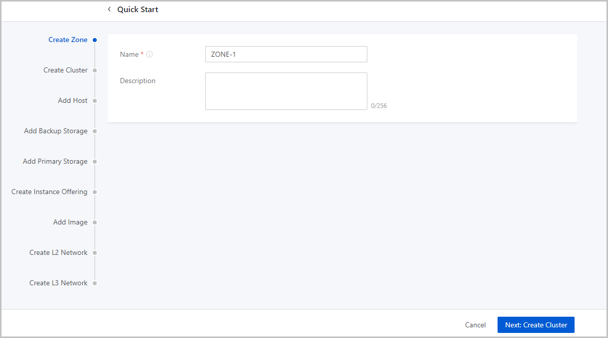
- Name: Enter a name for the zone.
- Description: Optional. Enter a description for the zone.
Create a Cluster
About this task
A cluster is a logical group of hosts (compute nodes). ZStack Cloud supports both KVM (native) and XDragon (baremetal) hypervisors.
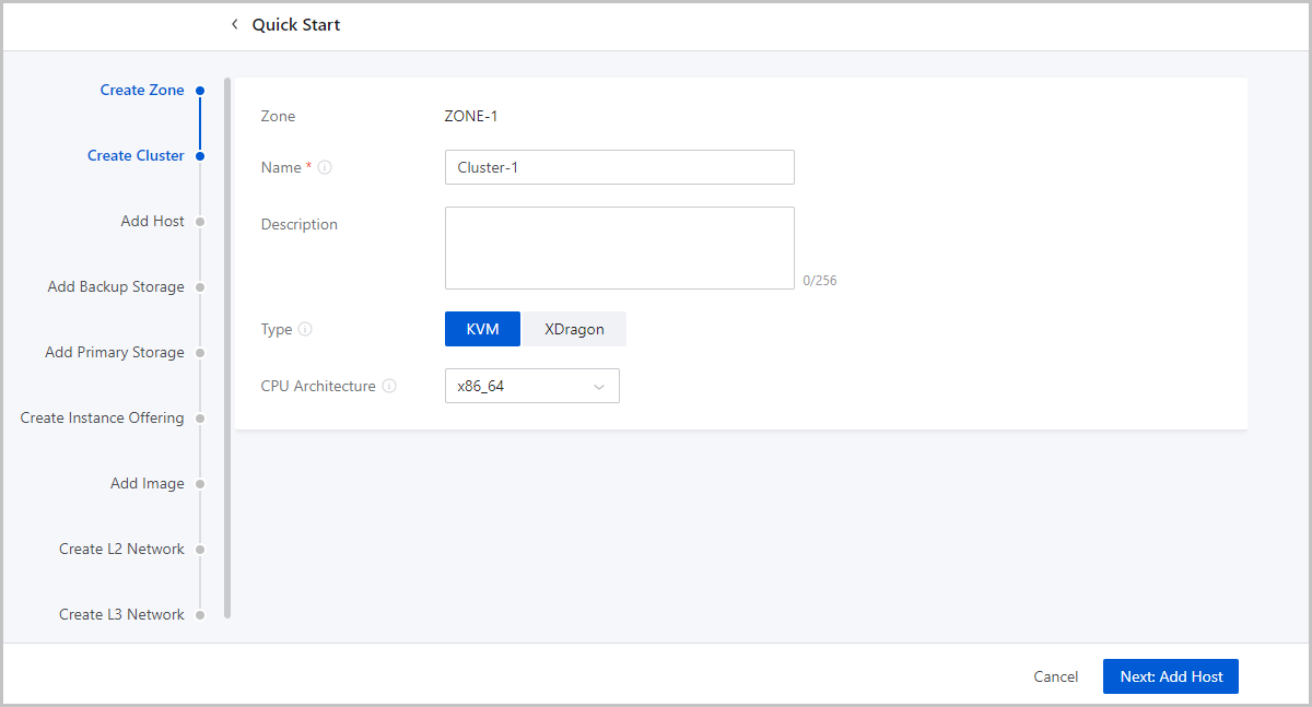
- Name: Enter a name for the cluster.
- Description: Optional. Enter a description for the cluster.
- Type: Optional. Select a hypervisor type for the server. Valid values: KVM and XDragon.
- CPU Architecture: Optional. Set the CPU architecture of the hosts in the cluster. If left blank, when you add the first host to the cluster, the CPU architecture of the hosts that you later add to the cluster must be the same as the architecture of this host. You cannot change the CPU architecture of the cluster any more.
Add a Host
About this task
A host provides compute, network, and storage resources for VM instances. ZStack Cube Ultimate supports more than 60 VM instances and 256 LUNs per host.
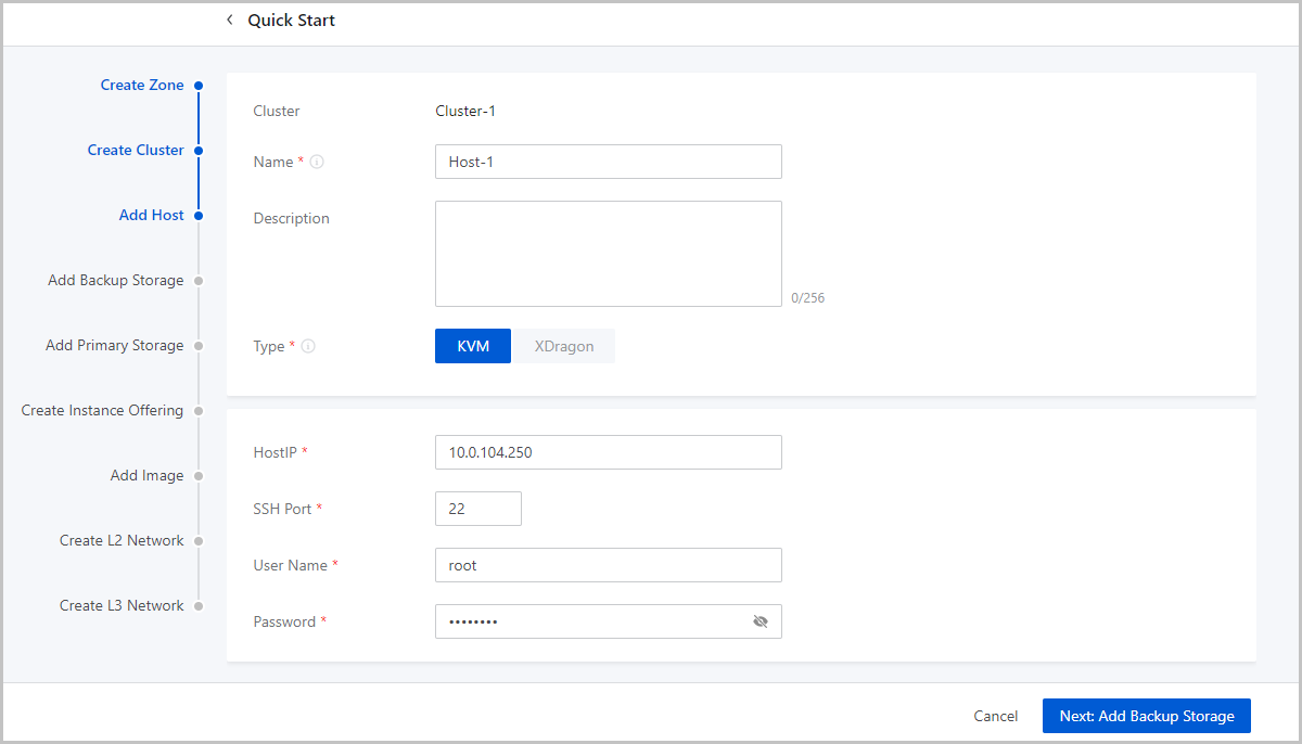
- Name: Enter a name for the host.
- Description: Optional. Enter a description for the host.
- Type: Select a hypervisor type for the server. Valid values: KVM and XDragon.
- Host IP: Enter the IP address of the host, for
example, 172.20.14.32.
- In the production environment, for stability and security concerns,
we recommend that you separate the management network from the
public network so that the management nodes and compute nodes reside
in independent networks and have independent IP addresses.
For example, if you use eth0 to connect a management network, ZStack Cube Ultimate uses the management network to communicate with compute nodes. If you use eth1 to connect to a public network, you can use the top aggregation switch to interconnect with the Internet.
- The separation of the management network and public network can maximize system security and ensure sufficient bandwidth for the management network.
- In the production environment, for stability and security concerns,
we recommend that you separate the management network from the
public network so that the management nodes and compute nodes reside
in independent networks and have independent IP addresses.
- SSH Port: Enter an SSH port for the host. Default: 22. If you do not specify an SSH port for the host, the system uses port 22 as the SSH port.
- User Name: Enter a username that has the sudo
permission for the host.
- If you specify a normal user, the user must have the sudo permission.
- We recommend that you use the adduser command to
create a normal user.The following script shows how to create a normal user and grant the user the sudo permission.
#Create a normal user named test
[root@localhost ~]# adduser test
#Grant the user the sudo permission
[root@localhost ~]# echo "test    ALL=(ALL)    NOPASSWD: ALL" >>/etc/sudoers
- Password: Enter the password of the user. Note the password is case sensitive.
- The configuration process may last several minutes.
- Error messages are prompted if errors occur.
What to do next
After completing the wizard, if you want to add more hosts to this cluster, make sure that the hosts to add are installed with the same system as the first host you add during the wizard, while the SSH ports, usernames, and the passwords can be the different. Note that ZStack Cube Ultimate supports not less than 256 LUNs on each host.
Add an Image Storage
An image storage is a storage server that stores VM image templates, including ISO image files.
- Name: Enter a name for the image storage.
- Description: Optional. Enter a description for the image storage.
- Storage Pool: Optional. Specify a storage pool.
- If you specify a storage pool, make sure that you have created the corresponding pool in the Ceph storage cluster in advance.
- If you do not specify a storage pool, the system automatically creates a pool in the Ceph storage cluster and use ths pool to create the image storage.
- SSH Port: Default: 22. If you have manually configured an SSH port for the node in advance, enter the port number you configured.
- Username: Default: root. If you have created a regular
user for the node, you can enter the corresponding user name.Note: Make sure
that you have configured sudo privileges for the regular user.
- Password: Enter the password of the user. The password is case-sensitive.
Click Next and the system creates a Ceph image storage.
Create an Instance Offering
About this task
An instance offering defines the number of vCPU cores, memory size, network bandwidth, and other configuration settings of VM instances.

- Name: Enter a name for the instance offering.
- Description: Optional. Enter a description for the instance offering.
- CPU: Enter the number of CPU cores of a VM instance.
- Memory: Set the size of the VM memory. Note that this value must be an integer. Unit: MB, GB, and TB.
- Host Allocation Strategy: Specify
how the Cloud allocates hosts when you create VM instances. Default
strategy: Host with min. running VMs.
- Host with min. running VMs: Allocates the host with the minimum number of running VM instances to create VM instances.
- Host with min. CPU utilization: Allocates the host with the
minimum CPU utilization to create VM instances.Note:
- The Cloud collects the host CPU loads over a period of time, calculates the CPU average utilization during this period, and then selects the host with the lowest CPU utilization to create VM instances.
- By default, the Cloud collects data at an interval of 10
minutes. You can change the collection cycle by using
the following method:
Choose and set Host CPU Utilization Collection Interval
- Host with min. memory utilization: Allocates the host with
the minimum memory utilization to create VM instances.Note:
- The Cloud collects the host memory loads over a period of time, calculates the memory average utilization during this period, and then selects the host with the lowest memory utilization to create VM instances.
- By default, the Cloud collects data at an interval of 10
minutes. You can change the collection cycle by using
the following method:
Choose and set Host Memory Utilization Collection Interval.
- Host with max. running VMs: Allocates the host with the maximum number of running VM instances to create VM instances. Before you can use this option, set the maximum number of VM instances that can run on a host. Then, the Cloud selects the host that meets the requirements to create VM instances. If no host is available, you will fail to create a VM instance.
- Host where the VM located last time: When you restart a
stopped VM instance, the system selects the host where the VM was
running last time. Note: If you start a VM instance for the first
time, the Cloud allocates a host randomly.
- Random allocation: Randomly allocates a host to create VM instances.
- Set Disk Bandwidth: Optional. Set
an upper limit for the I/O bandwidth of the root volume.If not set, the I/O bandwidth of the root volume is not limited. Unit: MB/s, GB/s, and TB/s. You can set the I/O bandwidth by using either of the following methods:
- Total Speed:
Set an upper limit for the total read and write speed of the root volume. Valid values: 1 MB/s to 100 GB/s, integer. Unit: MB/s and GB/s.
- Read/Write Speed:Set an upper limit for the read or write speed of the root volume.
- Read Speed: Optional. Set an upper limit for the read speed of the root volume. Valid values: 1 MB/s to 100 GB/s, integer. Unit: MB/s and GB/s.
- Write Speed: Optional. Set an upper limit for the write speed of the root volume. Valid values: 1 MB/s to 100 GB/s, integer. Unit: MB/s and GB/s.
- Total Speed:
- Set Disk IOPS: Optional. Set an upper limit for
reads/writes per second (IOPS) of a volume.If not set, the IOPS of a volume is not limited. You can set the IOPS by using either of the following methods:
- Total IOPS: Set an upper limit for the total IOPS of a volume.
- Read/Write IOPS: Set an upper limit for
the read or write IOPS of a volume.
- Read IOPS: Optional. Set an upper limit for the read IOPS of a volume.
- Write IOPS: Optional. Set an upper limit for the write IOPS of a volume.
- Set Network Bandwidth: Optional. Set an upper limit
for the network bandwidth of a VM instance.
- Upstream Bandwidth: Optional. Set an upper limit of the network bandwidth for uploading data from a VM instance. If not set, the network bandwidth of a VM instance is not limited. Valid values: 8 Kbps to 100 Gbps, integer. Unit: Kbps, Mbps, and Gbps.
- Downstream Bandwidth:
Optional. Set an upper limit of the network bandwidth for
downloading data from a VM instance. If not set, the network
bandwidth of a VM instance is not limited. Valid values: 8 Kbps to
100 Gbps, integer. Unit: Kbps, Mbps, and Gbps.Note: Before you make
any settings, make sure that you fully understand the
configurations of the disk bandwidth and network bandwidth.
Otherwise, you might fail to upload files to or download files
from a VM instance.
- Advanced Parameter: Optional.
Configure a JSON file to customize disk performance.Sample:
The preceding configuration settings can be divided into the following three parts:{ "allocate": { "primaryStorage": { "type": "Enter a primary storage type. Valid values: Ceph, LocalStorage, NFS, and SharedBlock.", "uuid": "Enter the UUID of the primary storage.", "poolNames": [ "Enter a name for the Ceph pool. Delete this parameter if you do not specify a Ceph primary storage." ] } "clusterUuid":"Enter the cluster UUID." }, "priceUserConfig": { "rootVolume": { "priceKeyName": "Set the billing name for the root volume. Make sure that the advanced parameter setting in the pricing list is consistent with the setting here. Otherwise, the corresponding billing entries cannot be generated." } }, "displayAttribute": { "rootVolume": { "diskType": "Set the display type of the root volume. You can view this parameter setting on the VM details page." } } }- Set a primary storage and cluster for the root
volume.
"allocate": { "primaryStorage": { "type": "Enter a primary storage type. Valid values: Ceph, LocalStorage, NFS, and SharedBlock.", "uuid": "Enter a primary storage UUID.", "poolNames": [ "Enter the name of a Ceph pool. Delete this parameter if you do not specify a Ceph primary storage." ] } "clusterUuid":"Enter a cluster UUID." }- type: Enter a primary storage type. Valid values: Ceph, LocalStorage, NFS, and SharedBlock. If you specify a Ceph primary storage, you can specify a Ceph pool.
- uuid: Enter a primary storage UUID.
- poolNames: Enter the name of a Ceph pool. Delete this parameter if you do not specify a Ceph primary storage.
Note: If you do not need to specify a primary storage or a
cluster, delete the corresponding codes. - Set a billing type for the root
volume.
"priceUserConfig": { "rootVolume": { "priceKeyName": "Set a billing name for the root volume. Make sure that advanced parameter setting in the pricing list is consistent with this setting. Otherwise, the corresponding billing entries cannot be generated." } }- priceKeyName: Set a billing name for the root volume. Make sure that advanced parameter setting in the pricing list is consistent with this setting. Otherwise, the corresponding billing entries cannot be generated.
Note: If you do not need billing settings, delete the preceding
parameter settings. - Set the display attribute of the root
volume.
"displayAttribute": { "rootVolume": { "diskType": "Set the display type for the root volume. You can view this parameter setting on the VM details page." } }- rootVolume: Set the display type for the root volume. You can view this parameter setting on the VM details page. You can also set multiple attributes in key-value pair format.
Note: If you do not need special display, delete the
corresponding codes.
- Set a primary storage and cluster for the root
volume.
Add an Image
About this task
An image is a template file used to create a VM instance or volume. Images are categorized into system images and volume images.
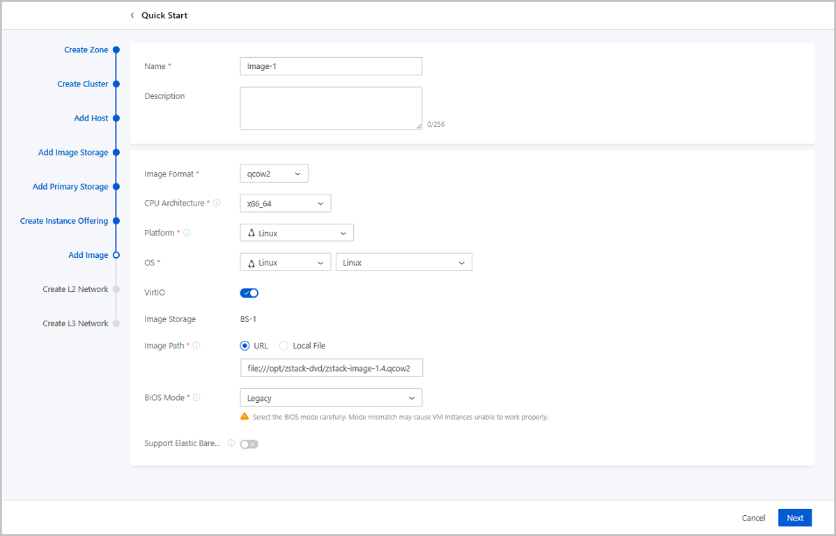
- Name: Enter a name for the image.
- Description: Optional. Enter a description for the image.
- Image Format: Select an image format. You can select qcow2, iso, or raw based on the image file property.
- Platform: Select an image platform type. Valid
values: Linux, Windows, and Other.Note: The Other platform type allows
compatibility with earlier versions of an OS.
- OS: Select an operating system that is consistent with the image.
- VirtIO: Choose whether to enable VirtIO according to your actual operating system and platform.
- Image Storage: Select an image storage.
- Image Path: Specify an image URL or upload a local
file:
- URL: Enter a specified URL to add an image.
You can enter a URL by using either of the following syntax:
- A URL that starts with http or https:
- Syntax: http://host[:port]/path/file or https://host[:port]/path/file.
- Example: http://cdn.zstack.io/product_downloads/images/zstack-image.qcow2
- A URL that starts with ftp:
- Syntax that does not specifies the user:
ftp://hostname[:port]/path/file.
Example: ftp://172.20.0.10/pub/zstack-image.qcow2.
- Syntax that specifies the user:
ftp://user:password@hostname[:port]/path/file.
Example: ftp://zstack:password@172.20.0.10/pub/zstack-image.qcow2.
- Syntax that does not specifies the user:
ftp://hostname[:port]/path/file.
- A URL that starts with sftp:
- Syntax that specifies the user identity:
sftp://user:password@hostname[:port]/path/file.
Example: sftp://root:password@172.20.0.10/pub/zstack-image.qcow2.
- User-identity-free syntax:
sftp://user@hostname[:port]/path/file.
Example: sftp://root@172.20.0.10/pub/zstack-image.qcow2.
- Syntax that specifies the user identity:
sftp://user:password@hostname[:port]/path/file.
- The absolute path of an image file that is stored on an
image storage. The image storage that stores the image file
can be an ImageStore image storage.
Example: file:///opt/zstack-dvd/zstack-image-1.4.qcow2.
Note:
- The image file to be added to the destination image storage must exist and the image storage needs to have access to the URL of the image file.
- If you enter a URL that starts with sftp and does not specify user identity, make sure that you enable mutual password-free SSH login between the image storage and SFTP server.
- For the progress bar and resumption from breakpoint
features:
- If you use an ImageStore image storage, a progress bar will appear to display the upload progress. In addition, upload resumption from breakpoints is also supported.
- If you use a Ceph image storage, a progress bar will appear to display the upload progress. However, upload resumption from breakpoints is not supported.
- If you specify a URL with the
file:/// syntax to add an
image:
- Ceph image storage does not support the file:/// syntax.
- The three forward slashes (/) in file:/// represents the absolute path of a file on an image storage. For example, if you specify the URL file:///opt/zstack-dvd/image-1.4.qcow2, you add the image file named image-1.4.qcow2 in the /opt/zstack-dvd path of an image storage to the Cloud.
- A URL that starts with http or https:
- Local File: Select a local image file that the current browser can access and upload the image file to the specified image storage. The image storage that stores the image file can be an ImageStore or Ceph image storage.
- URL: Enter a specified URL to add an image.
You can enter a URL by using either of the following syntax:
- BIOS Mode: Select a BIOS mode.
You can select the Legacy or UEFI mode.
- Legacy: This mode supports all operating systems (OSs) and ensures stable operation. We recommend you select this mode.
- UEFI: If the CPU architecture is AArch64 or MIPS64EL, you must select UEFI. This mode supports Windows and CentOS. Note if you use Windows 7 or Windows Server 2008, make sure that the operating system uses CSM.
Note: Mode mismatch may make VM instances unable
to work as expected. Select a mode according to your business needs:- If you add an image in the qcow2 or raw format, select the mode used when the image was created.
- If you add an image in the iso format, you can select either of the two modes. OS will be boot based on the selected mode.
- If you want to boot the OS of a VM instance in UEFI mode, we
recommend that you select a VM image that is created from one of
the OS listed in the following table.
OS BIOS Mode Supported Versions Windows UEFI - Windows 8 or later
UEFI - Windows 7
- Windows Server 2008 R2
Linux UEFI - CentOS 7.2
- CentOS 7.3
- CentOS 7.4 or later
- If you use a Window-based VM instance such
as Windows Server 2012 R2, Windows Server 2016, or Windows 10
that has its OS boot in UEFI mode, the following figure will be
displayed after you start the VM instance. In this case, press
any key to continue the installation of the OS. Otherwise, the
system will enter the UEFI Shell.If you have entered the UEFI Shell, run the following commands to exit the UEFI Shell:
Figure 2. Press Any Key to Continue 
Then press any key in a timely manner. Otherwise, the system will reenter the UEFI Shell.Shell> fs0: FS0:\> dir FS0:\> cd EFI FS0:\EFI\> cd BOOT FS0:\EFI\BOOT\> BOOTX64.EFI
- QEMU Guest Agent: Optional. Choose whether the
current image has installed QEMU Guest Agent (QGA).Note: If the image has
installed QGA and has set the agent as auto-start and you use the image
to create a VM instance, you can modify the passwords of this VM
instance, the clones of this VM instance, and the VM instances created
from the image that is created from this VM instance when these
instances are in the running state.
- Support Elastic Baremetal Instance:
Optional. Choose whether the image can be used to create an elastic
baremetal instance. If enabled, the image can be used to create an elastic
baremetal instance. Note: When you add an image of an elastic baremetal
instance, make sure:
- The image has installed the agent. Otherwise, after you use the image to create an elastic baremetal instance, you cannot open its console or modify its password. In addition, you cannot attach a volume or network to or detach them from the instance.
- The BIOS mode of the image is consistent with the system configuration. Default: UEFI. If you want to use Legacy, contact the technical support.
Create an L2 Network
About this task
An L2 network is a layer 2 broadcast domain used for layer 2 isolation. Generally, L2 networks are identified by names of devices on the physical network.
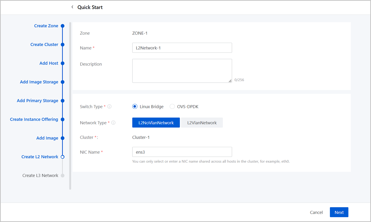
- Name: Enter a name for the L2 network.
- Description: Optional. Enter a description for the L2 network.
- Switch Type: Supported switch types include Linux Bridge and OVS-DPDK.
- Network Type: Choose a network type for the L2
network. Valid values: L2NoVlanNetwork, L2VlanNetwork.
- L2NoVlanNetwork
- If you do not need to use VLAN, select L2NoVlanNetwork.
- If you select L2NoVlanNetwork, the switch port connected by the specified NIC must be in the Access mode.
- L2VlanNetwork
- If you need to use VLAN on ZStack Cube Ultimate, select L2VlanNetwork.
- If you select L2VlanNetwork, the switch port connected by the specified NIC must be in the Trunk mode.
- VLAN ID: Enter a VLAN ID that matches the actual network configurations. Valid values: 1 to 4094.
- L2NoVlanNetwork
- Cluster: Display the the cluster to which the L2 network will be attached.
- NIC Name: Select or enter an NIC
name for the L2 network. For example, em01.Note: You can only select or
enter an NIC name shared across all hosts in the cluster.
Create an L3 Network
About this task
An L3 network includes IP ranges, gateway, DNS, and other network configurations that are used by VM instances.
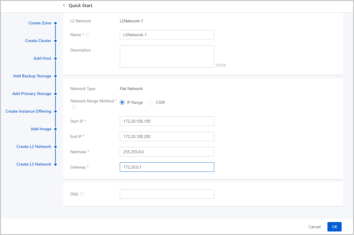
- Name: Enter a name for the L3 network.
- Description: Optional. Enter a description for the L3 network.
- Network Type: The wizard supports only flat network.
- Network Range Method: Select a method to add a
network range for the L3 network. You can select IP Range or CIDR.If you select IP Range, you need to set the following parameters:
- Start IP: Set a start IP address for the network range, for example, 172.20.108.100.
- End IP: Set an end IP address for the network range, for example, 172.20.108.200.
- Netmask: Set a netmask for the network range, for example, 255.255.0.0.
- Gateway: Set a gateway for the network range, for example, 172.20.0.1.
- DNS: Add a DNS server to provide domain name resolution services for the L3 network. You can specify 223.5.5.5, 8.8.8.8, or 114.114.114.114.
If you select CIDR, you need to set the following parameters:- CIDR: Set a CIDR block for the L3 network, for example, 192.168.108.1/24.
- Gateway: Set a gateway for the L3
network, for example, 192.168.108.1.Note:
- You can use the first or last IP address in the specified CIDR block as the gateway.
- If left blank, the first IP address in the specified CIDR block is used as the gateway.
- DNS: Add a DNS server to provide domain name resolution services for the L3 network. You can specify 223.5.5.5, 8.8.8.8, or 114.114.114.114.
What to do next
The wizard is completed.