Introduction
ZStack Cloud is built on Helix, a self-made virtualization kernel software that operates between the infrastructure layer and the upper-layer operating systems. It integrates essential components like hardware drivers, macro kernels, and virtual agents, shielding the differences among heterogeneous hardware. This releases operating systems from hardware driver dependencies, ensuring proper access to the heterogeneous hardware on the under layer. By doing so, Helix enhances hardware compatibility, high reliability, high availability, scalability, and performance of your virtual environment.
Currently, Helix has accommodated a variety of hardware, including Intel/AMD, Hygon, Kunpeng, FeiTeng, ShenWei, and Loongson. This makes it suitable for the finance, education, and government sectors, where controllability, stability, security, efficiency, and high performance are essential.
- h84r: ZStack-Cloud-x86_64-DVD-5.5.24-h84r.iso
This document describes the installation process based on an h84r ISO.
Environment Preparations
Prepare Software Packages
- ZStack Cloud
ISO:
- h84r: ZStack-Cloud-x86_64-DVD-5.5.24-h84r.iso
- Download address: Click here
- ZStack Cloud installation
package:
- Software: ZStack-Cloud-installer-5.5.24.bin
- Download address: Click here
- Multi-MN HA suite: Required only for a dual-MN deployment.
- Software: ZStack-Multinode-HA-Suite-5.5.24.tar.gz
- Download address: Click here
 Note: After you download the software packages, check the MD5
hash by using a MD5 checker to verify software integrity.
Note: After you download the software packages, check the MD5
hash by using a MD5 checker to verify software integrity.Hardware Requirements
Single-MN Deployment
| Device | Configuration Requirements |
|---|---|
| Server |
|
| Network Switch |
|
Dual-MN Deployment
| Device | Configuration Requirements | Description |
|---|---|---|
| Server | 2 servers | Used to deploy two MNs. We recommend that the two servers use the same hardware configuration. You can adjust the capacity ratio of the CPU, memory, and hardware according to actual business requirements. |
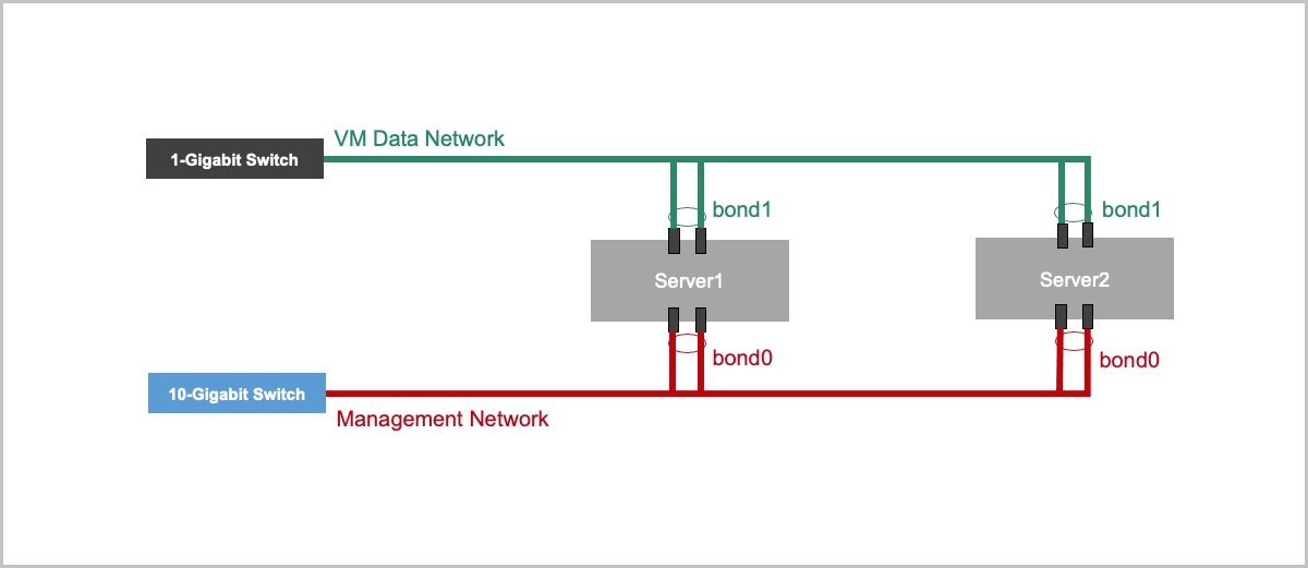
| NIC | Prepare NICs based on management network and VM data network planning. | The management network and VM data network use dedicated NICs or dedicated bonds. If you configure NIC bonding, configure LACP aggregation on the corresponding switch ports. |
| Network Switch | At least 1 management network switch and 1 VM data network switch | Select 1-Gigabit switches or 10-Gigabit switches based on your business scale, and complete VLAN and LACP configurations in advance. |
| Network Jumpers | Several Cat5 jumpers | Used to connect the MNs and switches. The cabling must be consistent with the network planning. |
| MN Real IP Address | 2 IP addresses | Used for system login, MN communication, and HA suite installation. |
| MN VIP | 1 IP address | The virtual IP address (VIP) is used to log in to the UI. Do not use the VIP to log in to a MN through SSH. |
| Netmask and Gateway | Prepare based on actual network planning. | The gateway must be provided by a physical network device. Meanwhile, the gateway is used to detect the network status. |
Burn Image to U Disk
About this task
This topic describes how to use Rufus to burn the prepared ISO image file to a U disk.Procedure
-
Use Rufus to open the ISO image file.
Open Rufus, select Disk or ISO image (Please select) from the Boot selection drop-down list, and click the Select button to open the downloaded ISO image file.
Figure 1. Use Rufus to Open ISO Image File 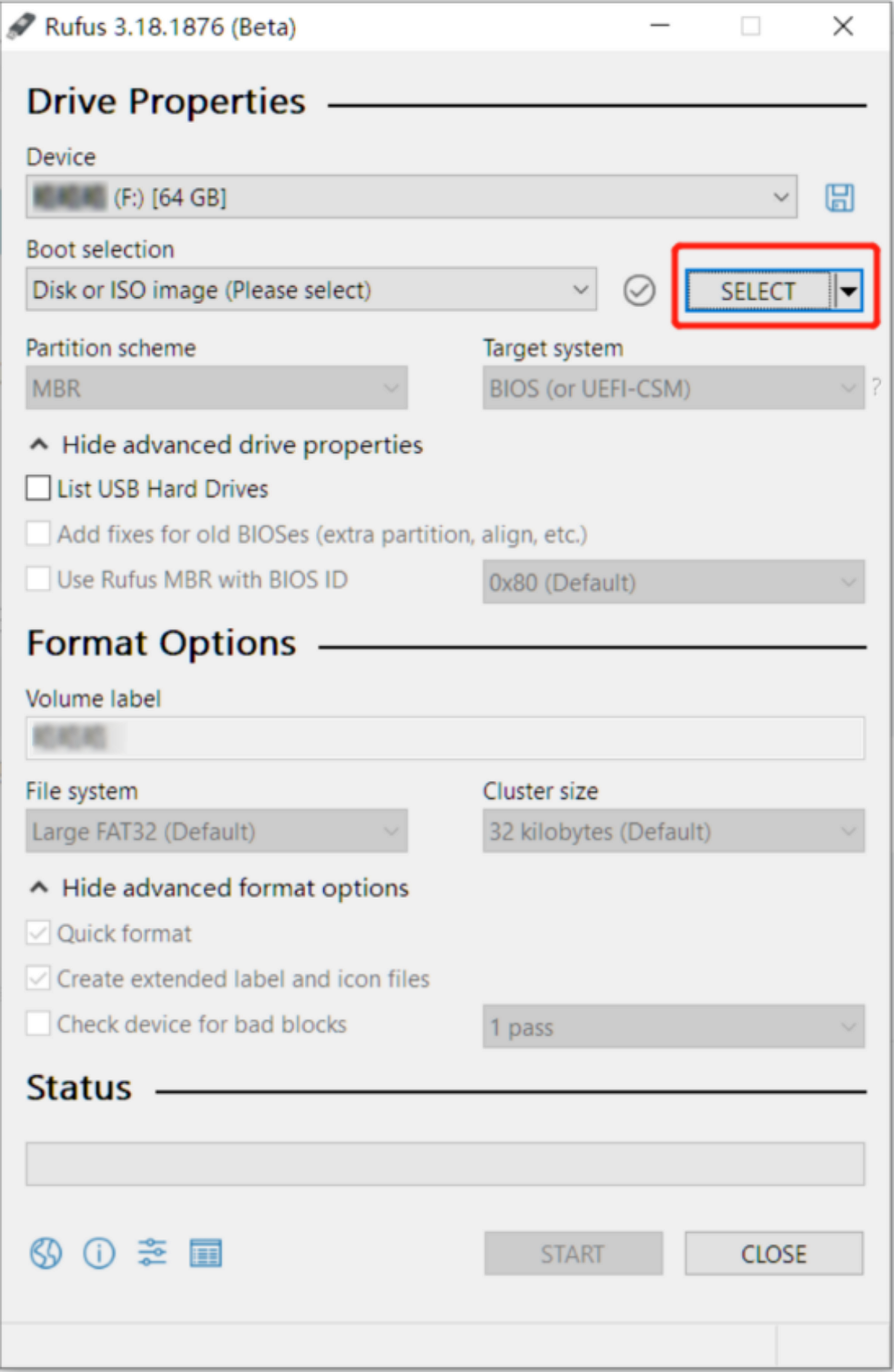
-
Write the image.
After you select the ISO image, use default settings, and choose Start.
Figure 2. Write Disk Image on Rufus 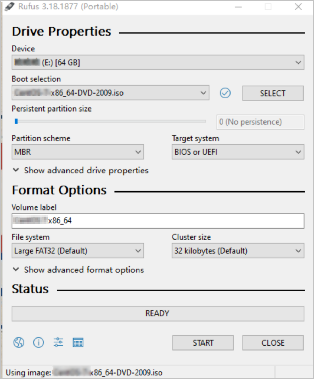
-
After you click Start, you will be
reminded of the risk that the disk data will be formatted. Click
OK to burn the image file.
Note: Before you burn the image file, make sure that you
backup the data on the U disk.
Figure 3. Confirm to Write ISO Image on Rufus 
- Then the U disk is used as the startup disk. This disk supports the Legacy and UEFI boot modes.
Deploy ZStack Cloud
ZStack Cloud supports single-MN deployment and dual-MN deployment. Select a suitable deployment process based on your scenario.
| Deployment Mode | Number of MNs | Scenario | Deployment Process |
|---|---|---|---|
| Single-MN Deployment | One MN | Applicable to quick experience, test verification, or small-scale environments. | Single-MN Deployment |
| Dual-MN Deployment | Two MNs | Improves the availability of the management plane through the management node VIP and HA service. This mode is applicable to production environments or scenarios that require high management node continuity. | Dual-MN Deployment |
Single-MN Deployment
About this task
This topic describes how to deploy a ZStack Cloud management node on one server. After deployment, you can access the ZStack Cloud UI by using the IP address of the management node.
Procedure
-
Configure the server.
- Make sure that the data on the disks of the server is backed up. The data will be overwritten during installation.
- Enter BIOS and enable the virtualization technology and hyper-threading options for CPU.
- Enter the RAID configuration page and configure the RAID level to provide a data redundancy mechanism that suits your business needs.
- Place the system startup disk in the first boot order.
-
Select the boot item.
On the ISO system boot interface, select the default option and then install the operating system.
Figure 1. System Boot 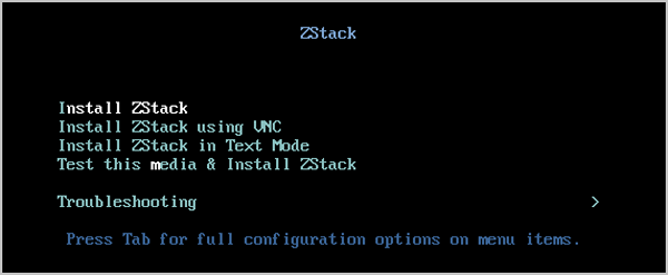
Note:
- ZStack Cloud provides the following installation methods: (graphic user interface) GUI, virtual network computing (VNC), and character user interface (CUI). We recommend that you use GUI to install the operating system.
- If the server does not have a VGA connector and only supports serial communication, you can use the VNC or CUI method.
-
Installation configuration summary.
The following figure displays system installation configurations. You can specify the configurations based on your needs. The default settings provided by ZStack Cloud are as follows:
- DATE&TIME: Asia/Shanghai timezone. We recommend that the admin checks the host time and sets to the current timezone and time.
- LANGUAGE: English (United States).
- KEYBOARD: English (US).
Figure 2. System Installation Interface 
-
Select the installation mode.
On the INSTALLATION SUMMARY page, click SOFTWARE SELECTION to enter the SOFTWARE SELECTION page. Select an installation mode on the page.
ZStack Cloud provides the following installation modes:- ZStack Enterprise Management NodeNote: We recommend that you
select this mode in the initial
installation.
- ZStack Community Management Node
- ZStack Compute Node
- ZStack Expert ModeNote:
- If you select this mode, after the system is installed, you are redirected to the terminal where you can customize installation of the cloud platform. If you select other modes, after the system is installed, the system automatically installs the cloud platform in the selected mode.
- No ZStack Local Repo: simplified installation. If you select this item, the ISO image file is not copied during installation and internal repo is not generated.
Figure 3. Select Installation Mode 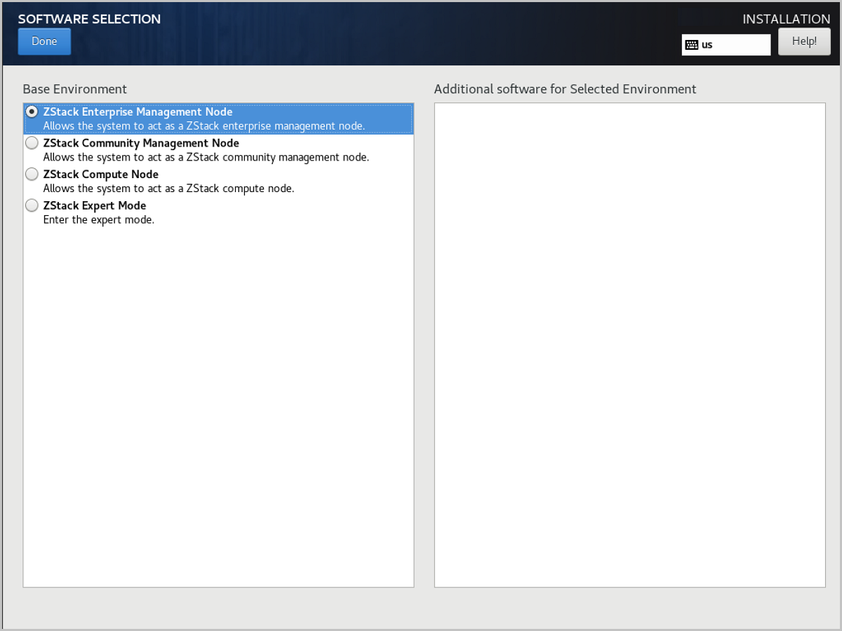
- ZStack Enterprise Management Node
-
Configure disk partitioning.
On the INSTALLATION SUMMARY page, click INSTALLATION DESTINATION to enter the INSTALLATION DESTINATION page.
Figure 4. Default Disk Partitioning 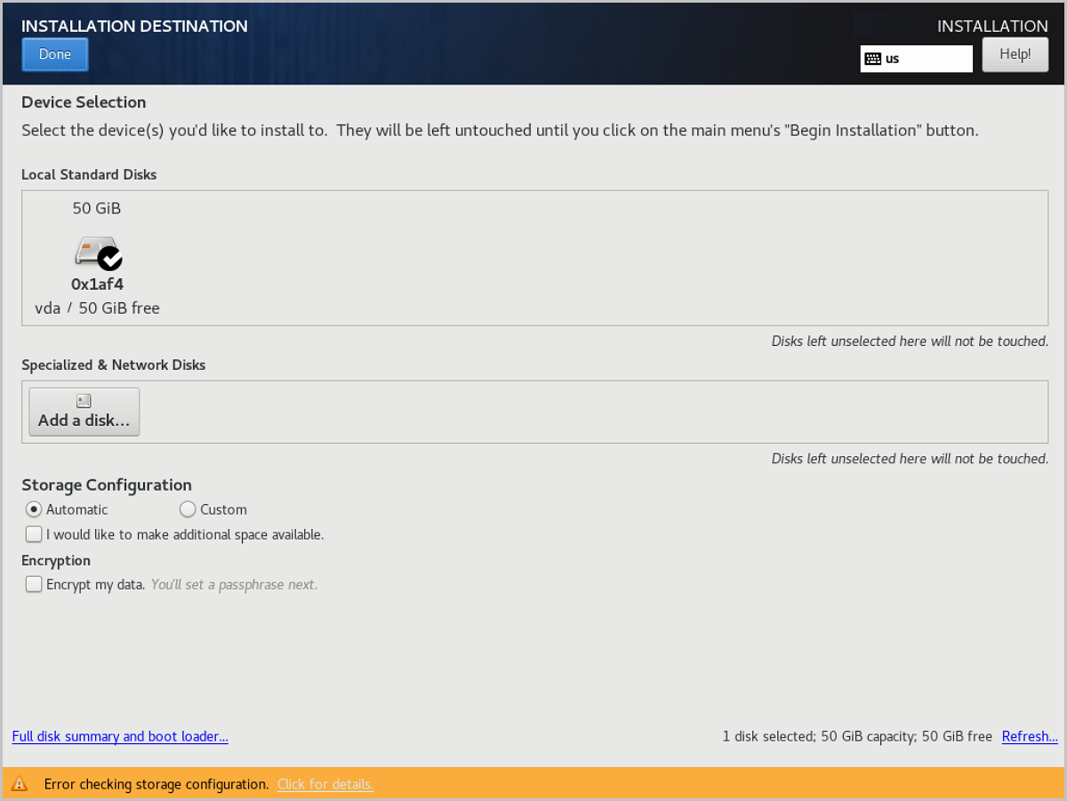
Note: We recommend that you only configure the
system disk on the page. After the system is installed, you can
configure other disks.ZStack Cloud sets partitioning to Automatically configure partitioning by default. If you want to customize partitioning, set the parameters based on the BIOS boot mode:- UEFI mode
- /boot: stores the core files required for Linux startup. We recommend that you distribute 1 GB to the directory.
- /boot/efi: stores UEFI boot file. We recommend that you distribute 500 MB to the directory.
- swap: swap. We recommend that you distribute 32 GB to the swap.
- /: Linux system root. We recommend that you distribute the rest of the space to the directory.
- Legacy mode
- /boot: stores the core files required for Linux startup. We recommend that you distribute 1 GB to the directory.
- swap: swap. We recommend that you distribute 32 GB to the swap.
- /: Linux system root. We recommend that you distribute the rest of the space to the directory.
Note:
- We recommend that the total disk capacity for ZStack Cloud be greater than 300 GB.
- In Legacy mode, if the capacity of the system disk is greater than 2 TB, you need to configure the BIOS boot partition for the support of the GPT partition. In UEFI mode, you do not need to configure this item and the GPT partition is supported.
- UEFI mode
-
Configure the network.
This step describes how to configure a static IP address for a NIC and enable auto-activation of NIC. This configuration is used only for proof of concept (POC). In the production environment, we recommend that you configure NIC bonding. For more information, see Network Bonding (Optional)
- Configure a static IP address.
- On the INSTALLATION SUMMARY page, choose . Then the Editing ens3 page is displayed.
On the page, choose . Then you can manually assign an IP
address.Note: You can also use DHCP to automatically obtain
an IP address.
- Click Add to add an IP entry, configure
the IP address, subnet, and gateway, and then click
save to save the configurations.
Figure 5. Configure Static Address 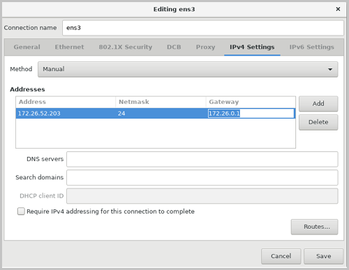
- On the INSTALLATION SUMMARY page, choose . Then the Editing ens3 page is displayed.
On the page, choose . Then you can manually assign an IP
address.
- Configure NIC auto-activation.
On the Editing ens3 page, choose . Then the auto-activation is enabled.
Figure 6. Configure NIC Auto-Activation 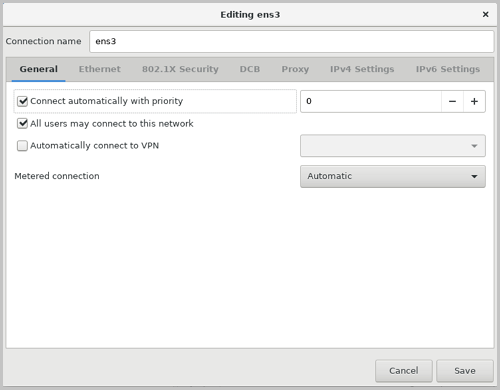
- Configure a static IP address.
-
Set a password.
On the INSTALLATION SUMMARY page, click Root Password to set a root password.
Figure 7. Set Password 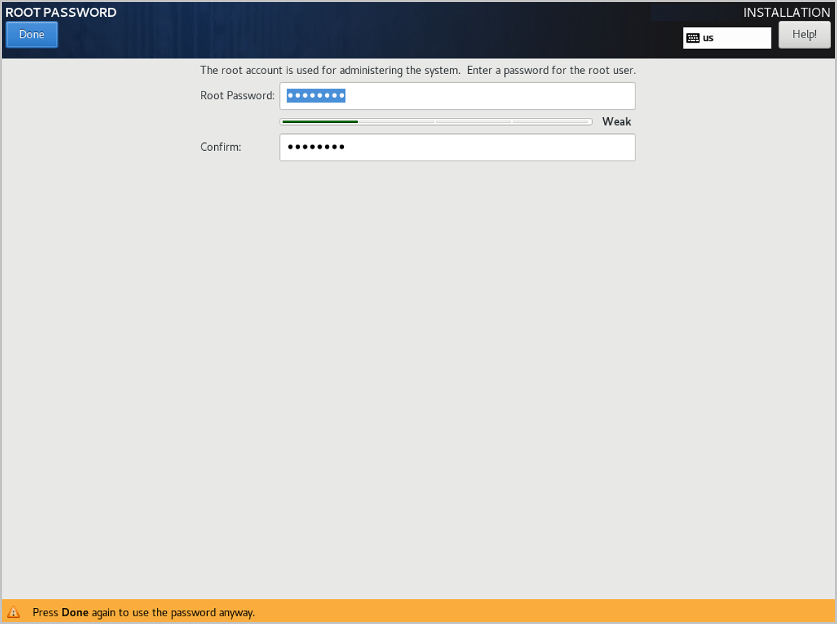
-
Start installation.
Go back to the INSTALLATION SUMMARY page, click Begin Installation to install the operating system.
-
Enter the system.
After the system is installed, click Restart and enter the custom system of ZStack Cloud.
Dual-MN Deployment
A dual-MN deployment uses the management node VIP as the unified access entry. After deployment, the administrator can access the ZStack Cloud UI by using the VIP. If the current active MN becomes unavailable, the VIP can switch to the other MN.
Deployment Process
| Step | Task | Reference |
|---|---|---|
| 1 | Install ZStack Cloud MNs on two servers. | Install Operating System |
| 2 | Configure the management network for the two MNs, and plan the management node VIP. | Configure Networks |
| 3 | Install the Multi-MN HA suite on one of the MNs. | Install HA Suite |
| 4 | Log in by using the management node VIP and initialize the cloud. | Verify the Dual-MN Deployment |
Key Planning Items
| Planning Item | Example | Description |
|---|---|---|
| Real IP Address of MN1 | 192.168.195.200 | Used for SSH login, HA suite installation, and communication between MNs. |
| Real IP Address of MN2 | 192.168.196.125 | Used for SSH login, HA suite installation, and communication between MNs. |
| Management Node VIP | 192.168.199.151 | Used to log in to the ZStack Cloud UI. Do not use the VIP to log in to a MN through SSH. |
| Arbitration Gateway | 192.168.0.1 | Used to detect the network status. The gateway must be provided by a physical network device. |
Install Operating System
About this task
Use the ZStack Cloud ISO to install two servers as MNs. The operating system installation method is the same for both MNs.
Procedure
-
Prepare a bootable U disk.
Prepare the ZStack Cloud ISO according to Prepare Software Packages, and burn the ISO to a U disk according to Burn Image to U Disk.
-
Configure the server.
- Make sure that the data on the disks of the server is backed up. The data will be overwritten during installation.
- Enter BIOS and enable the virtualization technology and hyper-threading options for CPU.
- Enter the RAID configuration page and configure the RAID level to provide a data redundancy mechanism that suits your business needs.
- Place the system startup disk in the first boot order.
-
Select the boot item.
On the ISO system boot interface, select the default option and then install the operating system.
Figure 1. System Boot
Note:
- ZStack Cloud provides the following installation methods: (graphic user interface) GUI, virtual network computing (VNC), and character user interface (CUI). We recommend that you use GUI to install the operating system.
- If the server does not have a VGA connector and only supports serial communication, you can use the VNC or CUI method.
-
Installation configuration summary.
The following figure displays system installation configurations. You can specify the configurations based on your needs. The default settings provided by ZStack Cloud are as follows:
- DATE&TIME: Asia/Shanghai timezone. We recommend that the admin checks the host time and sets to the current timezone and time.
- LANGUAGE: English (United States).
- KEYBOARD: English (US).
Figure 2. System Installation Interface
-
Select the installation mode.
On the INSTALLATION SUMMARY page, click SOFTWARE SELECTION to enter the SOFTWARE SELECTION page. Select an installation mode on the page.
ZStack Cloud provides the following installation modes:- ZStack Enterprise Management NodeNote: We recommend that you
select this mode in the initial
installation.
- ZStack Community Management Node
- ZStack Compute Node
- ZStack Expert ModeNote:
- If you select this mode, after the system is installed, you are redirected to the terminal where you can customize installation of the cloud platform. If you select other modes, after the system is installed, the system automatically installs the cloud platform in the selected mode.
- No ZStack Local Repo: simplified installation. If you select this item, the ISO image file is not copied during installation and internal repo is not generated.
Figure 3. Select Installation Mode
- ZStack Enterprise Management Node
-
Configure disk partitioning.
On the INSTALLATION SUMMARY page, click INSTALLATION DESTINATION to enter the INSTALLATION DESTINATION page.
Figure 4. Default Disk Partitioning
Note: We recommend that you only configure the
system disk on the page. After the system is installed, you can
configure other disks.ZStack Cloud sets partitioning to Automatically configure partitioning by default. If you want to customize partitioning, set the parameters based on the BIOS boot mode:- UEFI mode
- /boot: stores the core files required for Linux startup. We recommend that you distribute 1 GB to the directory.
- /boot/efi: stores UEFI boot file. We recommend that you distribute 500 MB to the directory.
- swap: swap. We recommend that you distribute 32 GB to the swap.
- /: Linux system root. We recommend that you distribute the rest of the space to the directory.
- Legacy mode
- /boot: stores the core files required for Linux startup. We recommend that you distribute 1 GB to the directory.
- swap: swap. We recommend that you distribute 32 GB to the swap.
- /: Linux system root. We recommend that you distribute the rest of the space to the directory.
Note:
- We recommend that the total disk capacity for ZStack Cloud be greater than 300 GB.
- In Legacy mode, if the capacity of the system disk is greater than 2 TB, you need to configure the BIOS boot partition for the support of the GPT partition. In UEFI mode, you do not need to configure this item and the GPT partition is supported.
- UEFI mode
-
Set a password.
On the INSTALLATION SUMMARY page, click Root Password to set a root password.
Figure 5. Set Password
-
Start installation.
Go back to the INSTALLATION SUMMARY page, click Begin Installation to install the operating system.
-
Enter the system.
After the system is installed, click Restart and enter the custom system of ZStack Cloud.
Configure Networks
About this task
Configure the management network for the two MNs. ZStack Cloud provides a convenient network configuration script in the /usr/local/bin/ directory. You can use this script to quickly configure the interface, bond, and bridge information.
This topic uses the following network planning as an example. Replace the sample information with your actual network information during deployment:
| Node | NIC | Bond | Bridge | IP Address | Gateway |
|---|---|---|---|---|---|
| MN1 | eth0, eth1 | bond0 | br_bond0 | 192.168.195.200 | 192.168.0.1 |
| MN2 | eth0, eth1 | bond0 | br_bond0 | 192.168.196.125 | 192.168.0.1 |
| VIP | - | - | br_bond0 | 192.168.199.151 | - |
| Node | NIC | Bond | Bridge | Description |
|---|---|---|---|---|
| MN1 | em1, em2 | bond1 | - | Used to carry the VM data network. |
| MN2 | em1, em2 | bond1 | - | Used to carry the VM data network. |
Note:
- The virtual IP address (VIP) is used to log in to the UI. Do not use the VIP to log in to a MN through SSH.
- The gateway must be provided by a physical network device. Meanwhile, the gateway is used to detect the network status.
- In production environments, we recommend that you use a management network
bridge to carry the VIP, such as
br_bond0. - If the MNs are also used as compute nodes, we recommend that you configure a dedicated VM data network.
Procedure
-
Configure the management network of MN1.
Log in to MN1 and run the following commands:
[root@localhost ~]# zs-bond-lacp -c bond0 [root@localhost ~]# zs-nic-to-bond -a bond0 eth0 [root@localhost ~]# zs-nic-to-bond -a bond0 eth1 [root@localhost ~]# zs-network-setting -b bond0 192.168.195.200 255.255.0.0 192.168.0.1 [root@localhost ~]# zs-show-network -
Configure the management network of MN2.
Log in to MN2, run the similar commands, and replace the IP address with the IP address of MN2:
[root@localhost ~]# zs-bond-lacp -c bond0 [root@localhost ~]# zs-nic-to-bond -a bond0 eth0 [root@localhost ~]# zs-nic-to-bond -a bond0 eth1 [root@localhost ~]# zs-network-setting -b bond0 192.168.196.125 255.255.0.0 192.168.0.1 [root@localhost ~]# zs-show-network -
Configure the VM data network.
If the MNs are also used as compute nodes, you can configure the VM data network on both MNs. On MN1, run the following commands as an example:
[root@localhost ~]# zs-bond-lacp -c bond1
[root@localhost ~]# zs-nic-to-bond -a bond1 em1
[root@localhost ~]# zs-nic-to-bond -a bond1 em2
[root@localhost ~]# zs-show-network
Log in to MN2, run the similar commands, and replace
em1andem2with the actual NIC names.Note: After you attach NICs to a bond, you must configure LACP aggregation on
the corresponding switch ports. Otherwise, the network communication might
be abnormal. -
Check management network connectivity.
After the network configuration is complete, complete the following checks:
Check Item Requirement MN Connectivity The real IP addresses of the two MNs can ping each other. Gateway Connectivity Both MNs can ping the arbitration gateway. VIP Planning The VIP is not occupied by other devices, and is in a reachable network range with the real IP addresses of the two MNs and the gateway. Switch Configuration If link aggregation is used, LACP aggregation has been configured on the corresponding switch ports. Note:
- The management network is used for MN communication and VIP carrying. The VM data network does not need to carry the VIP.
- The preceding network planning is sample data. Replace the NIC names, IP addresses, netmask, and gateway based on your actual network environment.
Install HA Suite
After the operating system and network configuration are complete on both MNs, install the Multi-MN HA suite on one of the MNs to switch to a dual-MN HA environment.
| Method | Scenario | Reference |
|---|---|---|
| Use the Command Line | Applicable when there are only a few parameters and you want to complete the installation at one time. | Use the Command Line |
| Use a Configuration File | Applicable when you need to save installation parameters, review configurations, or reuse the same configuration. | Use a Configuration File |
Note: If you use the same configuration to install the HA suite, the command line method has
higher priority than the configuration file method.Use the Command Line
About this task
This topic describes how to install the HA suite by using command line parameters. The following example uses MN1 (192.168.195.200) as the active MN and MN2 (192.168.196.125) as the standby MN.
Procedure
-
Import and decompress the HA suite.
Import the HA suite to MN1, and run the following commands to decompress the suite:
[root@localhost ~]# ls ZStack-Multinode-HA-Suite-5.5.24.tar.gz [root@localhost ~]# tar zxvf ZStack-Multinode-HA-Suite-5.5.24.tar.gz zsha2 zstack-hamon -
Install the HA suite.
On MN1, run the following commands:
[root@localhost ~]# chmod +x zsha2 zstack-hamon
[root@localhost ~]# ./zsha2 install-ha -nic br_bond0 -gateway 192.168.0.1 -slave "root:password@192.168.196.125" \
-vip 192.168.199.151 -myip 192.168.195.200 -db-root-pw zstack.mysql.password -time-server 192.168.196.125 -cidr 192.168.0.0/16 -yes
Note:
- After the installation command is executed, the database of the active and backup MNs will be automatically backed up, and then the suite will be installed.
- During the installation process, the database of the standby MN will be overwritten by that of the active MN. Confirm that the active and standby MNs are selected correctly.
- To install the HA suite, you need to put zsha2 and zstack-hamon in the same directory.
-
Confirm the installation parameters.
Parameter Description -nicThe name of the physical device. This parameter is used to configure a VIP. In production environments, this parameter is generally a management network bridge, such as br_bond0.-gatewayThe arbitration gateway of the active and backup MNs. -slaveSpecifies the standby MN. The format is "root:password@peer_ip". If the root password contains special shell characters, escape these characters according to shell rules.-vipSpecifies the management node VIP, which is used to access the ZStack Cloud UI. -myipSpecifies the IP address of the MN on which the installation command is executed. -db-root-pwThe database root password of the active and standby MNs. Make sure that both MNs share the same root password. -time-serverSpecifies one or more time synchronization servers. -cidrSpecifies the network range, which must cover the real IP addresses of the two MNs, the VIP, and the gateway. We recommend that you specify the network range based on your actual network planning. -yesIndicates that the current configuration is confirmed and the installation is allowed. -
Check the MN status.
After the HA suite is initialized, run the following command to view the MN status:
[root@localhost ~]# zsha2 statusConfirm that the current active MN has obtained the VIP (
Owns virtual
                            address: yes
), and that the gateway, VIP, peer MN, Keepalived, HA monitoring service, database, and MN services are in a normal state.
Use a Configuration File
About this task
If you need to save HA installation parameters as a configuration file, install the HA suite by using a configuration file. The following example uses MN1 (192.168.195.200) as the active MN and MN2 (192.168.196.125) as the standby MN.
Procedure
-
Import and decompress the HA suite.
Import the HA suite to MN1, and run the following commands to decompress the suite:
[root@localhost ~]# tar zxvf ZStack-Multinode-HA-Suite-5.5.24.tar.gz [root@localhost ~]# chmod +x zsha2 zstack-hamon -
Generate and modify the configuration file.
Run the following commands to generate the configuration file, and modify the parameters based on your actual deployment planning:
[root@localhost ~]# ./zsha2 sample-config > zs-install.config
[root@localhost ~]# vi zs-install.config
{ "gateway": "192.168.0.1", "virtualIp": "192.168.199.151", "myIp": "192.168.195.200", "peerIp": "192.168.196.125", "peerSshUser": "root", "peerSshPass": "password", "peerSshPort": 22, "dbRootPass": "zstack.mysql.password", "interface": "br_bond0", "timeServer": "192.168.196.125" }Configuration Item Description gatewayThe arbitration gateway of the active and backup MNs. virtualIpSpecifies the management node VIP, which is used to access the ZStack Cloud UI. myIpSpecifies the IP address of the MN on which the installation command is executed. peerIpSpecifies the IP address of the peer MN. peerSshUser/peerSshPassSpecifies the SSH username and password of the peer MN. dbRootPassSpecifies the root password of the active and backup MNs. Make sure that both MNs share the same root password. interfaceThe name of the physical device. This parameter is used to configure a VIP. In production environments, this parameter is generally a management network bridge. timeServerSpecifies a time synchronization server. -
Install the HA suite.
Run the following command:
[root@localhost ~]# ./zsha2 install-ha -config zs-install.configNote:
- After the installation command is executed, the database of the active and backup MNs will be automatically backed up, and then the suite will be installed.
- During the installation process, the database of the standby MN will be overwritten by that of the active MN. Confirm that the active and standby MNs are selected correctly.
-configinstalls the HA suite by initializing the configuration file.
-
Check the MN status.
After the HA suite is initialized, run the following command to view the MN status:
[root@localhost ~]# zsha2 statusConfirm that the current active MN has obtained the VIP (
Owns virtual
                            address: yes
), and that the gateway, VIP, peer MN, Keepalived, HA monitoring service, database, and MN services are in a normal state.
Verify the Dual-MN Deployment
About this task
After the HA suite is installed, verify the dual-MN deployment status first. After the verification is passed, go to Initialization by Wizard to complete the wizard settings.
Procedure
-
Check the HA status.
Run the following command on either MN:
[root@localhost ~]# zsha2 statusConfirm the following status according to the command output:
Check Item Expected Result VIP Status The current active MN returns Owns virtual address: yes.MN Service The MN service, UI service, and database service are in a normal state. Node Connectivity The gateway, VIP, and peer MN are reachable. -
Verify UI access.
Enter
http://management_node_vip:5000in the address bar of Chrome 66 or later, and confirm that the ZStack Cloud UI login page is displayed.For subsequent access to the ZStack Cloud UI, continue to use the management node VIP. After the verification is passed, see Initialization by Wizard to complete the cloud initialization.
Getting Started
Initialization by Wizard
- If you stop using the wizard or delete key resources during initial setup, you are not directed to use the wizard again.
- In a dual-MN deployment, use the management node VIP to access the UI.
- We recommend that you use the wizard to complete the basic environment configurations of ZStack Cloud.
Create a Zone
About this task
A zone is a logical group of resources such as clusters, L2 networks, and primary storage. Zone is the largest resource scope defined in the Cloud.
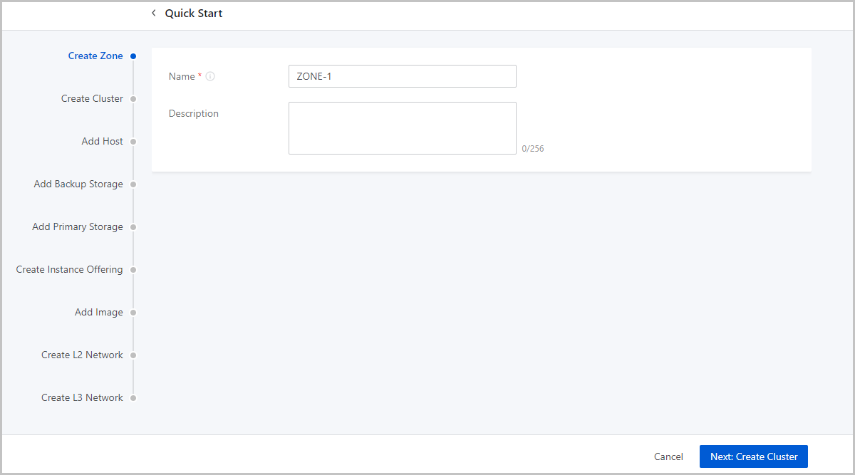
- Name: Enter a name for the zone.
- Description: Optional. Enter a description for the zone.
Create a Cluster
About this task
A cluster is a logical group of hosts (compute nodes). ZStack Cloud supports both KVM (native) and XDragon (baremetal) hypervisors.
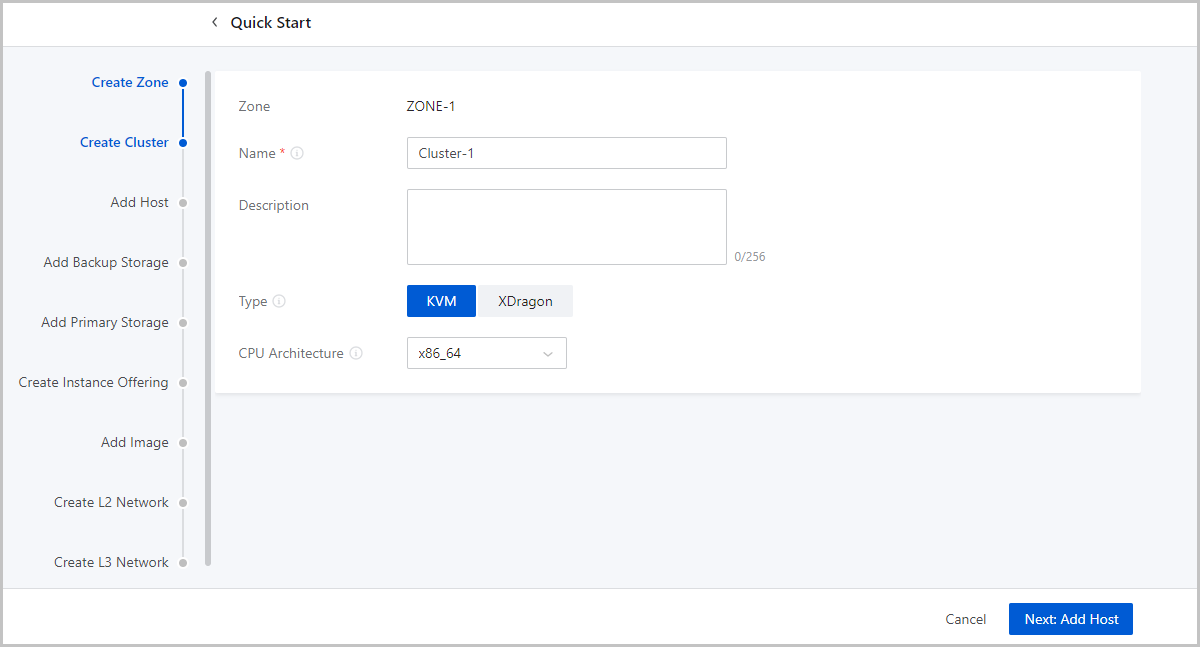
- Name: Enter a name for the cluster.
- Description: Optional. Enter a description for the cluster.
- Type: Optional. Select a hypervisor type for the server. Valid values: KVM and XDragon.
- CPU Architecture: Optional. Set the CPU architecture of the hosts in the cluster. If left blank, when you add the first host to the cluster, the CPU architecture of the hosts that you later add to the cluster must be the same as the architecture of this host. You cannot change the CPU architecture of the cluster any more.
Add a Host
About this task
A host provides compute, network, and storage resources for VM instances. ZStack Cloud supports more than 60 VM instances and 256 LUNs per host.
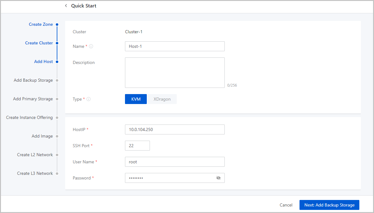
- Name: Enter a name for the host.
- Description: Optional. Enter a description for the host.
- Type: Select a hypervisor type for the server. Valid values: KVM and XDragon.
- Host IP: Enter the IP address of the host, for
example, 172.20.14.32.
- In the production environment, for stability and security concerns,
we recommend that you separate the management network from the
public network so that the management nodes and compute nodes reside
in independent networks and have independent IP addresses.
For example, if you use eth0 to connect a management network, ZStack Cloud uses the management network to communicate with compute nodes. If you use eth1 to connect to a public network, you can use the top aggregation switch to interconnect with the Internet.
- The separation of the management network and public network can maximize system security and ensure sufficient bandwidth for the management network.
- In the production environment, for stability and security concerns,
we recommend that you separate the management network from the
public network so that the management nodes and compute nodes reside
in independent networks and have independent IP addresses.
- SSH Port: Enter an SSH port for the host. Default: 22. If you do not specify an SSH port for the host, the system uses port 22 as the SSH port.
- User Name: Enter a username that has the sudo
permission for the host.
- If you specify a normal user, the user must have the sudo permission.
- We recommend that you use the adduser command to
create a normal user.The following script shows how to create a normal user and grant the user the sudo permission.
#Create a normal user named test
[root@localhost ~]# adduser test
#Grant the user the sudo permission
[root@localhost ~]# echo "test    ALL=(ALL)    NOPASSWD: ALL" >>/etc/sudoers
- Password: Enter the password of the user. Note the password is case sensitive.
- The configuration process may last several minutes.
- Error messages are prompted if errors occur.
What to do next
After completing the wizard, if you want to add more hosts to this cluster, make sure that the hosts to add are installed with the same system as the first host you add during the wizard, while the SSH ports, usernames, and the passwords can be the different. Note that ZStack Cloud supports not less than 256 LUNs on each host.
Add an Image Storage
An image storage is a storage server that stores VM image templates, including ISO image files.
- ImageStore: stores images in the format of chips and supports incremental storage.
- Sftp: stores images in the format of files.
- Ceph: stores images in the format of distributed blocks.
Configure an image storage based on your business needs.
ImageStore
About this task
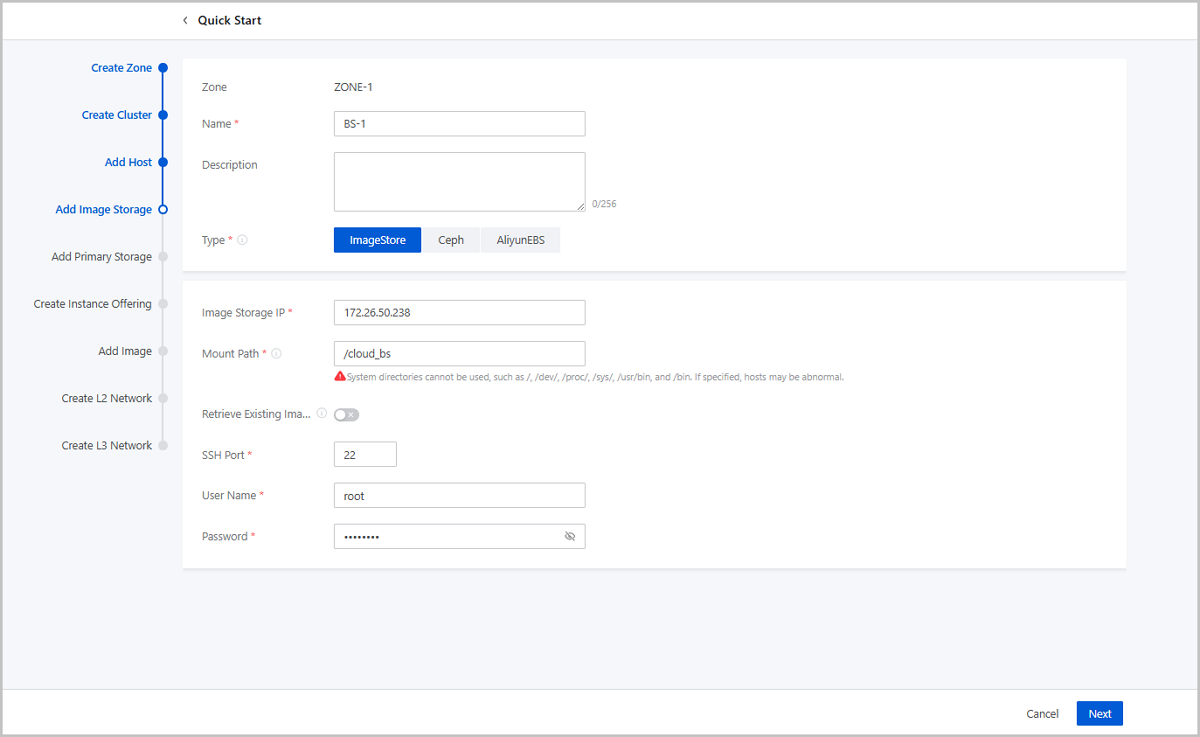
- Name: Enter a name for the image storage.
- Description: Optional. Enter a description for the image storage.
- Type: Select ImageStore.
- Image Storage IP: Enter the image storage IP.
- In the production environment, for the security and stability concerns, we recommend that you separate the management network from the public network.
- You can assign a management network IP address to the image storage to save the public network bandwidth.
- If the public network has ten-gigabits of bandwidth, you can assign
a public network IP address to the image storage. This increases the
image transmission rate between the image storage and compute
nodes.
In most cases, adding or saving an image consumes large amounts of bandwidth. If you assign a public network IP address to the image storage, we recommend that you add or save an image during network idle time.
- You can set a dedicated storage network if necessary.
- Mount Path: Specify a path on the image storage that corresponds to sufficient storage space, for example, /ImageStore_bs.
- Retrieve Existing Image: Choose whether to retrieve images stored in the specified path.
- SSH Port: Enter an SSH port for the image storage. Default: 22. If you do not specify an SSH port for the image storage, the system uses port 22 as the SSH port.
- User Name: Enter a username. By default, root user is
used. You can also specify a normal user.
- If you do not specify a normal user for the image storage, the root user is used.
- If you specify a normal user, the user must have the sudo permission.
- Password: Enter the password of the user. Note the password is case sensitive.
Ceph
About this task
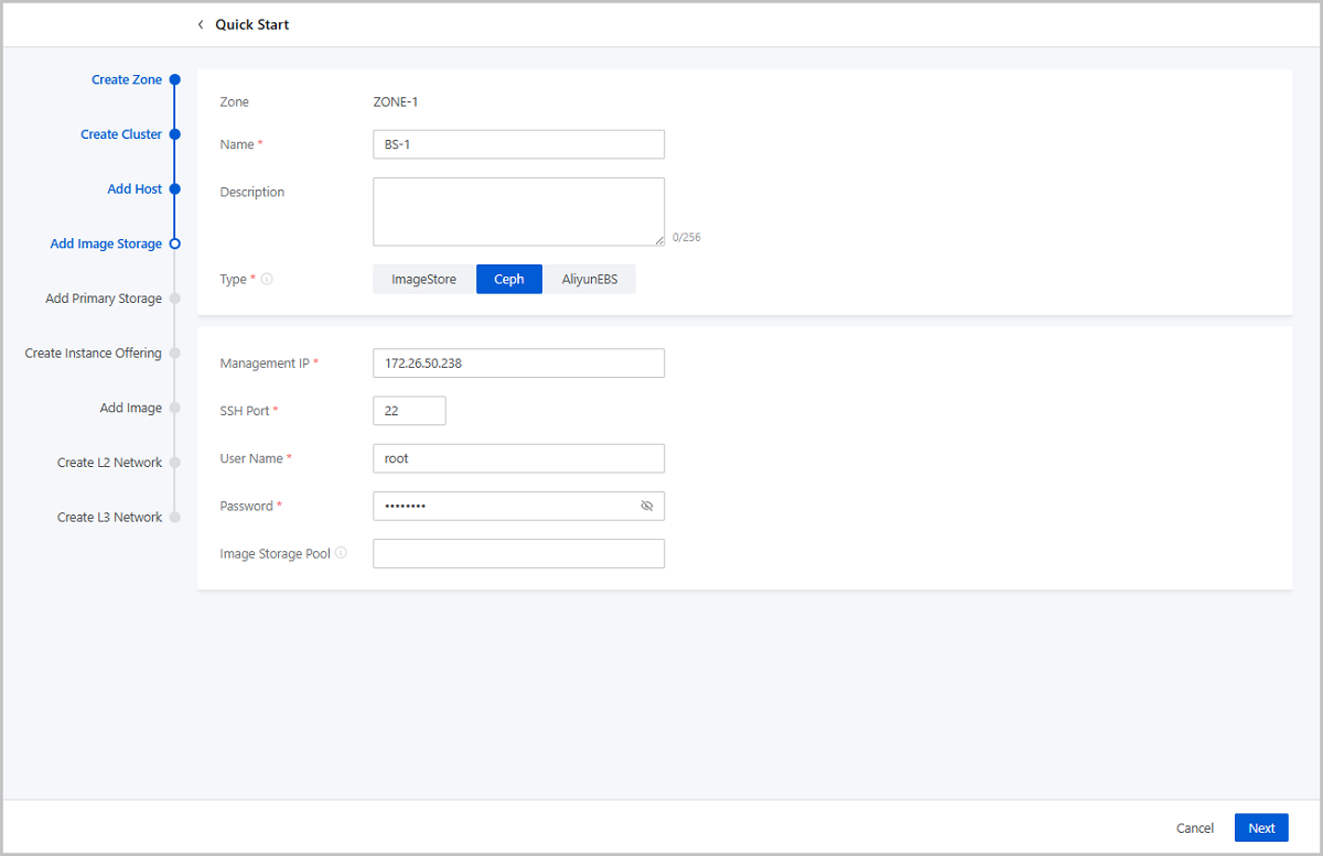
- Name: Enter a name for the image storage.
- Description: Optional. Enter a description for the image storage.
- Type: Select Ceph.
- Monitor Node IP: Enter the IP address of the Ceph monitor node.
- SSH Port: Enter an SSH port for the monitor node. Default: 22. If you do not specify an SSH port for the monitor node, the system uses port 22 as the SSH port.
- User Name: Enter a username. By default, root user is
used. You can also specify a normal user.
- If you do not specify a normal user for the image storage, the root user is used.
- If you specify a normal user, the user must have the sudo permission.
- Password: Enter the password of the user. Note the password is case sensitive.
- Pool UUID: Optional. Specify a storage pool for the
Ceph image storage.
- Before you specify a pool, you need to create a pool in the Ceph storage cluster.
- If left blank, a storage pool is created automatically.
Add a Primary Storage
A primary storage is one or more servers that store volume files of VM instances. These files include root volume snapshots, data volume snapshots, image caches, root volumes, and data volumes.
- LocalStorage: uses the disks of the host for storage.
- Network Sharing Storage: supports NFS, Shared Mount Point, and Ceph.
- NFS allows you to store files by using the NFS protocol.
- Shared Mount Point provides network sharing storage by using popular distributed file systems including MooseFS, GlusterFS, OCFS2, and GFS2.
- Ceph stores files in the format of distributed blocks.
Note:
- If you use ImageStore image storage, you can use a primary storage of the LocalStorage, NFS, Share Mount Point, or Ceph type.
- If you use a Ceph image storage, you can use only Ceph primary storage.
If you need to add a primary storage of the SharedBlock type, exit the wizard and add a primary storage on the primary storage management page.
LocalStorage
About this task
If you add a LocalStorage primary storage, all hosts are configured with the same directory that you specify.
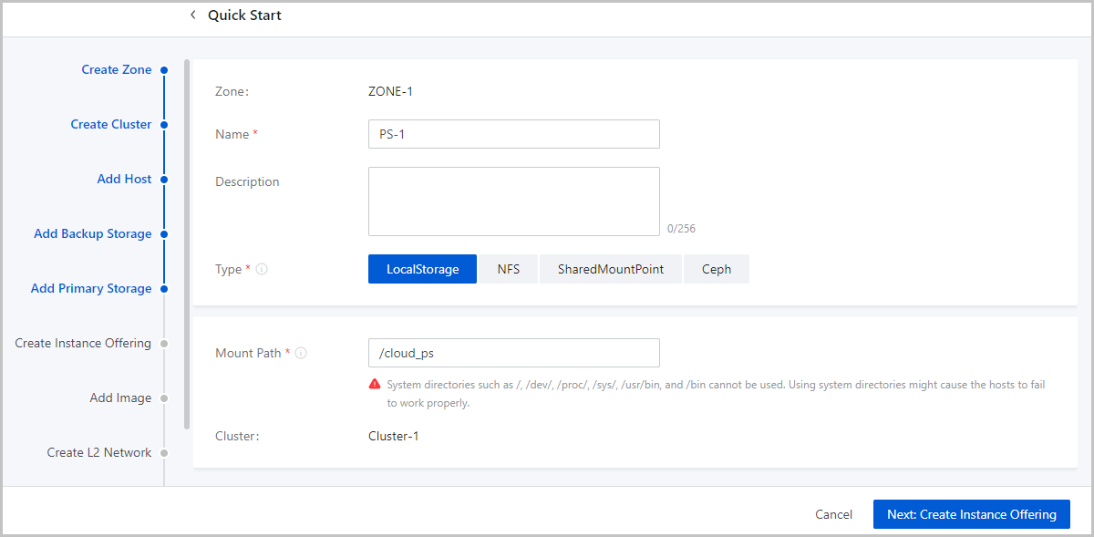
- Name: Enter a name for the primary storage.
- Description: Optional. Enter a description for the primary storage.
- Type: Select LocalStorage.
- Mount Path: Specify a path on the primary storage Note:
- If the specified path does not exist on the primary storage, the system automatically creates the path.
- You cannot specify the following system paths. Otherwise, a host
error may occur:
- /
- /dev/
- /proc/
- /sys/
- /usr/bin
- /bin
NFS
About this task
If you use NFS primary storage, ZStack Cloud mounts the shared NFS directory to all the hosts. The hosts need to be granted read and write permissions on the mounted directory.
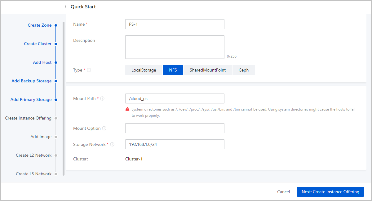
- Name: Enter a name for the primary storage.
- Description: Optional. Enter a description for the primary storage.
- Type: Select NFS.
- Mount Path: Specify the URL of a shared directory on
the NFS server a path on the primary storage. You can specify an IP address
or domain name.Note:
- The URL is in the format of NFS_Server_IP:/NFS_Share_folder, for example, 192.168.0.1:/nfs_root.
- You need to configure access permissions on the shared directory on the NFS server side in advance.
- To ensure the security of the NFS server, we recommend that you configure security rules to implement access control.
- You need to use the
showmount -ecommand on the NFS server to check the shared directory. - You cannot specify the following system paths. Otherwise, a host
error may occur:
- /
- /dev/
- /proc/
- /sys/
- /usr/bin
- /bin
- Mount Option: To add mount options, make sure that
these options are supported by the NFS server.Note:
- Separate each option with a comma (,), for example, nfsvers=3,sec=sys,tcp,intr,timeo=5. This example means that NFS Version 3 is used on the NFS server, the standard UNIX authentication mechanism is used, TCP is used as the transmission protocol, an NFS call can be interrupted in case of an exception, and the timeout is 0.5 seconds (5/10).
- To specify mount options, you can refer to the content in the -o option of mount.
- You can set the options according to the commonly used mount options on clients. If the configured option conflict with the NFS server, the configuration on the server side shall prevail.
- Storage Network: Specify a network for the shared
storage. You can use the management network.Note:
- If you specify a dedicated storage network, you need to specify the CIDR of the network.
- You can use the storage network to check the health status of VM instances.
- Click Next to complete the addition of the NFS primary storage.
Shared Mount Point
Prerequisites
If you use Shared Mount Point (SMP) primary storage on ZStack Cloud, you can use distributed file systems such as MooseFS, GlusterFS, OCFS2, and GFS2 to provide network sharing storage.
About this task
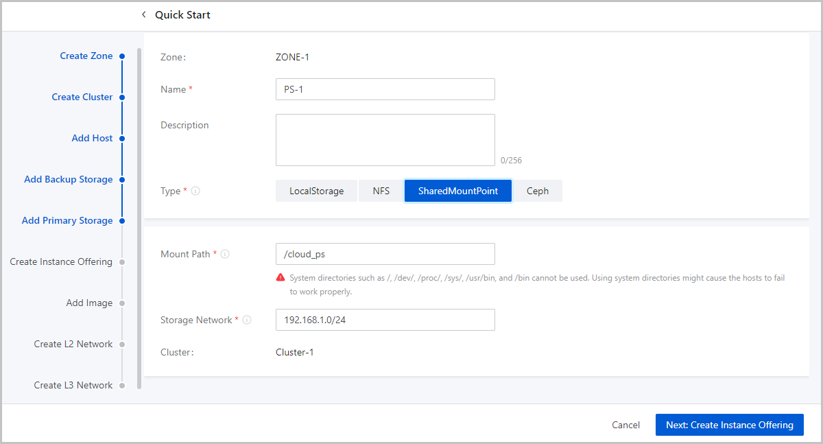
- Name: Enter a name for the primary storage.
- Description: Optional. Enter a description for the primary storage.
- Type: Select SharedMountPoint.
- Mount Path: Specify the URL of the shared directory mounted on hosts.
- Storage Network: Specify a network for the shared
storage. You can use the management network.Note:
- If you specify a dedicated storage network, you need to specify the CIDR of the network.
- You can use the storage network to check the health status of VM instances.
Ceph
About this task
ZStack Cloud allows you to store files in Ceph primary storage in the format of blocks. If you add a Ceph primary storage, you need to add a Ceph primary storage, you need to add a Ceph or ImageStore image storage and configure Ceph distributed storage in advance.

- Name: Enter a name for the primary storage.
- Description: Optional. Enter a description for the primary storage.
- Type: Select Ceph.
- Cephx: Choose whether to use keys for authentication.Note:
- By default, the Cephx authentication feature is enabled.
- If you disable Cephx, the authentication feature is disabled.
- If storage nodes and compute nodes reside in secure networks, you can disable Cephx to avoid authentication failures.
- Make sure that the Cephx configuration on Ceph storage is consistent with this configuration. If Cephx is enabled on Ceph storage but disabled on the cloud platform, VM instances may fail to be created.
- IP Address: Enter the IP address of the Ceph monitor node.
- SSH Port: Enter the SSH port of the Ceph monitor node. Default: 22.
- User Name: Enter the username of the Ceph monitor node.
- Password: Enter the password for the specified username.
- Image Cache Pool: Enter an image cache pool. If left blank, the system automatically creates a pool.
- Data Volume Pool: Enter a data volume pool. If left blank, the system automatically creates a pool.
- Root Volume Pool: Enter a root volume pool. If left blank, the system automatically creates a pool.
- Storage Network: Specify a network for the shared
storage. You can use the management network.Note:
- If you specify a dedicated storage network, you need to specify the CIDR of the network.
- You can use the storage network to check the health status of VM instances.
Create an Instance Offering
About this task
An instance offering defines the number of vCPU cores, memory size, network bandwidth, and other configuration settings of VM instances.
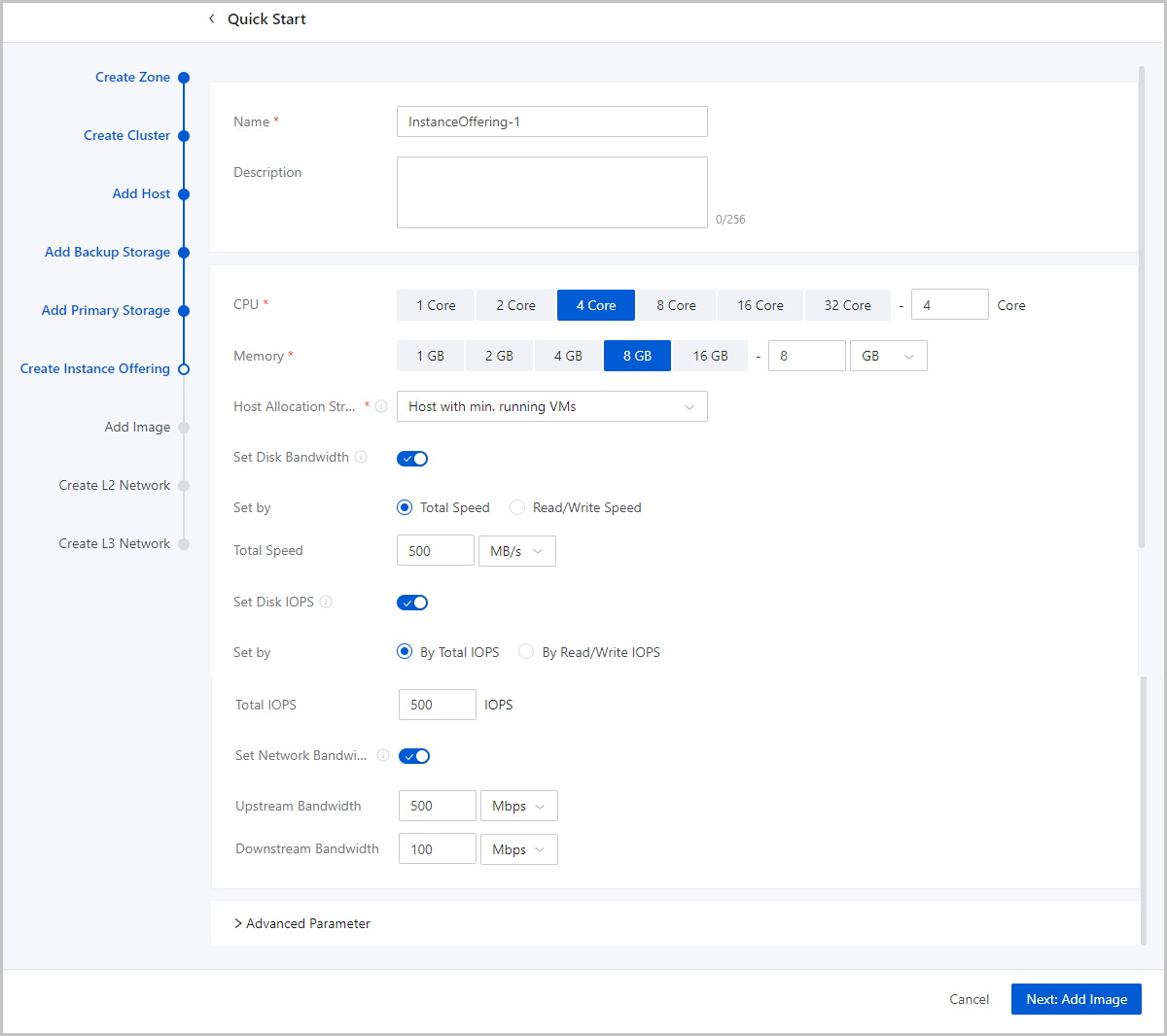
- Name: Enter a name for the instance offering.
- Description: Optional. Enter a description for the instance offering.
- CPU: Enter the number of CPU cores of a VM instance.
- Memory: Set the size of the VM memory. Note that this value must be an integer. Unit: MB, GB, and TB.
- Host Allocation Strategy: Specify
how the Cloud allocates hosts when you create VM instances. Default
strategy: Host with min. running VMs.
- Host with min. running VMs: Allocates the host with the minimum number of running VM instances to create VM instances.
- Host with min. CPU utilization: Allocates the host with the
minimum CPU utilization to create VM instances.Note:
- The Cloud collects the host CPU loads over a period of time, calculates the CPU average utilization during this period, and then selects the host with the lowest CPU utilization to create VM instances.
- By default, the Cloud collects data at an interval of 10
minutes. You can change the collection cycle by using
the following method:
Choose and set Host CPU Utilization Collection Interval
- Host with min. memory utilization: Allocates the host with
the minimum memory utilization to create VM instances.Note:
- The Cloud collects the host memory loads over a period of time, calculates the memory average utilization during this period, and then selects the host with the lowest memory utilization to create VM instances.
- By default, the Cloud collects data at an interval of 10
minutes. You can change the collection cycle by using
the following method:
Choose and set Host Memory Utilization Collection Interval.
- Host with max. running VMs: Allocates the host with the maximum number of running VM instances to create VM instances. Before you can use this option, set the maximum number of VM instances that can run on a host. Then, the Cloud selects the host that meets the requirements to create VM instances. If no host is available, you will fail to create a VM instance.
- Host where the VM located last time: When you restart a
stopped VM instance, the system selects the host where the VM was
running last time. Note: If you start a VM instance for the first
time, the Cloud allocates a host randomly.
- Random allocation: Randomly allocates a host to create VM instances.
- Set Disk Bandwidth: Optional. Set
an upper limit for the I/O bandwidth of the root volume.If not set, the I/O bandwidth of the root volume is not limited. Unit: MB/s, GB/s, and TB/s. You can set the I/O bandwidth by using either of the following methods:
- Total Speed:
Set an upper limit for the total read and write speed of the root volume. Valid values: 1 MB/s to 100 GB/s, integer. Unit: MB/s and GB/s.
- Read/Write Speed:Set an upper limit for the read or write speed of the root volume.
- Read Speed: Optional. Set an upper limit for the read speed of the root volume. Valid values: 1 MB/s to 100 GB/s, integer. Unit: MB/s and GB/s.
- Write Speed: Optional. Set an upper limit for the write speed of the root volume. Valid values: 1 MB/s to 100 GB/s, integer. Unit: MB/s and GB/s.
- Total Speed:
- Set Disk IOPS: Optional. Set an upper limit for
reads/writes per second (IOPS) of a volume.If not set, the IOPS of a volume is not limited. You can set the IOPS by using either of the following methods:
- Total IOPS: Set an upper limit for the total IOPS of a volume.
- Read/Write IOPS: Set an upper limit for
the read or write IOPS of a volume.
- Read IOPS: Optional. Set an upper limit for the read IOPS of a volume.
- Write IOPS: Optional. Set an upper limit for the write IOPS of a volume.
- Set Network Bandwidth: Optional. Set an upper limit
for the network bandwidth of a VM instance.
- Upstream Bandwidth: Optional. Set an upper limit of the network bandwidth for uploading data from a VM instance. If not set, the network bandwidth of a VM instance is not limited. Valid values: 8 Kbps to 100 Gbps, integer. Unit: Kbps, Mbps, and Gbps.
- Downstream Bandwidth:
Optional. Set an upper limit of the network bandwidth for
downloading data from a VM instance. If not set, the network
bandwidth of a VM instance is not limited. Valid values: 8 Kbps to
100 Gbps, integer. Unit: Kbps, Mbps, and Gbps.Note: Before you make
any settings, make sure that you fully understand the
configurations of the disk bandwidth and network bandwidth.
Otherwise, you might fail to upload files to or download files
from a VM instance.
- Advanced Parameter: Optional.
Configure a JSON file to customize disk performance.Sample:
The preceding configuration settings can be divided into the following three parts:{ "allocate": { "primaryStorage": { "type": "Enter a primary storage type. Valid values: Ceph, LocalStorage, NFS, and SharedBlock.", "uuid": "Enter the UUID of the primary storage.", "poolNames": [ "Enter a name for the Ceph pool. Delete this parameter if you do not specify a Ceph primary storage." ] } "clusterUuid":"Enter the cluster UUID." }, "priceUserConfig": { "rootVolume": { "priceKeyName": "Set the billing name for the root volume. Make sure that the advanced parameter setting in the pricing list is consistent with the setting here. Otherwise, the corresponding billing entries cannot be generated." } }, "displayAttribute": { "rootVolume": { "diskType": "Set the display type of the root volume. You can view this parameter setting on the VM details page." } } }- Set a primary storage and cluster for the root
volume.
"allocate": { "primaryStorage": { "type": "Enter a primary storage type. Valid values: Ceph, LocalStorage, NFS, and SharedBlock.", "uuid": "Enter a primary storage UUID.", "poolNames": [ "Enter the name of a Ceph pool. Delete this parameter if you do not specify a Ceph primary storage." ] } "clusterUuid":"Enter a cluster UUID." }- type: Enter a primary storage type. Valid values: Ceph, LocalStorage, NFS, and SharedBlock. If you specify a Ceph primary storage, you can specify a Ceph pool.
- uuid: Enter a primary storage UUID.
- poolNames: Enter the name of a Ceph pool. Delete this parameter if you do not specify a Ceph primary storage.
Note: If you do not need to specify a primary storage or a
cluster, delete the corresponding codes. - Set a billing type for the root
volume.
"priceUserConfig": { "rootVolume": { "priceKeyName": "Set a billing name for the root volume. Make sure that advanced parameter setting in the pricing list is consistent with this setting. Otherwise, the corresponding billing entries cannot be generated." } }- priceKeyName: Set a billing name for the root volume. Make sure that advanced parameter setting in the pricing list is consistent with this setting. Otherwise, the corresponding billing entries cannot be generated.
Note: If you do not need billing settings, delete the preceding
parameter settings. - Set the display attribute of the root
volume.
"displayAttribute": { "rootVolume": { "diskType": "Set the display type for the root volume. You can view this parameter setting on the VM details page." } }- rootVolume: Set the display type for the root volume. You can view this parameter setting on the VM details page. You can also set multiple attributes in key-value pair format.
Note: If you do not need special display, delete the
corresponding codes.
- Set a primary storage and cluster for the root
volume.
Add an Image
About this task
An image is a template file used to create a VM instance or volume. Images are categorized into system images and volume images.
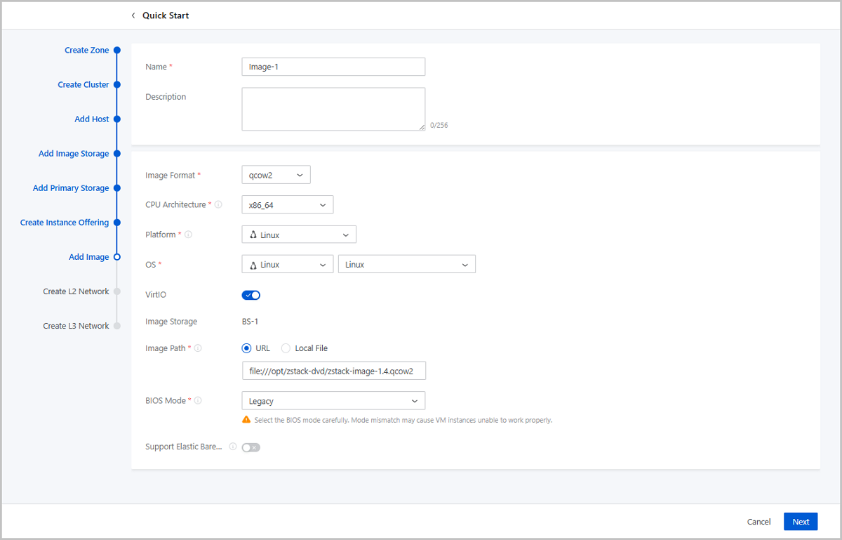
- Name: Enter a name for the image.
- Description: Optional. Enter a description for the image.
- Image Format: Select an image format. You can select qcow2, iso, or raw based on the image file property.
- Platform: Select an image platform type. Valid
values: Linux, Windows, and Other.Note: The Other platform type allows
compatibility with earlier versions of an OS.
- OS: Select an operating system that is consistent with the image.
- VirtIO: Choose whether to enable VirtIO according to your actual operating system and platform.
- Image Storage: Select an image storage.
- Image Path: Specify an image URL or upload a local
file:
- URL: Enter a specified URL to add an image.
You can enter a URL by using either of the following syntax:
- A URL that starts with http or https:
- Syntax: http://host[:port]/path/file or https://host[:port]/path/file.
- Example: http://cdn.zstack.io/product_downloads/images/zstack-image.qcow2
- A URL that starts with ftp:
- Syntax that does not specifies the user:
ftp://hostname[:port]/path/file.
Example: ftp://172.20.0.10/pub/zstack-image.qcow2.
- Syntax that specifies the user:
ftp://user:password@hostname[:port]/path/file.
Example: ftp://zstack:password@172.20.0.10/pub/zstack-image.qcow2.
- Syntax that does not specifies the user:
ftp://hostname[:port]/path/file.
- A URL that starts with sftp:
- Syntax that specifies the user identity:
sftp://user:password@hostname[:port]/path/file.
Example: sftp://root:password@172.20.0.10/pub/zstack-image.qcow2.
- User-identity-free syntax:
sftp://user@hostname[:port]/path/file.
Example: sftp://root@172.20.0.10/pub/zstack-image.qcow2.
- Syntax that specifies the user identity:
sftp://user:password@hostname[:port]/path/file.
- The absolute path of an image file that is stored on an
image storage. The image storage that stores the image file
can be an ImageStore image storage.
Example: file:///opt/zstack-dvd/zstack-image-1.4.qcow2.
Note:
- The image file to be added to the destination image storage must exist and the image storage needs to have access to the URL of the image file.
- If you enter a URL that starts with sftp and does not specify user identity, make sure that you enable mutual password-free SSH login between the image storage and SFTP server.
- For the progress bar and resumption from breakpoint
features:
- If you use an ImageStore image storage, a progress bar will appear to display the upload progress. In addition, upload resumption from breakpoints is also supported.
- If you use a Ceph image storage, a progress bar will appear to display the upload progress. However, upload resumption from breakpoints is not supported.
- If you specify a URL with the
file:/// syntax to add an
image:
- Ceph image storage does not support the file:/// syntax.
- The three forward slashes (/) in file:/// represents the absolute path of a file on an image storage. For example, if you specify the URL file:///opt/zstack-dvd/image-1.4.qcow2, you add the image file named image-1.4.qcow2 in the /opt/zstack-dvd path of an image storage to the Cloud.
- A URL that starts with http or https:
- Local File: Select a local image file that the current browser can access and upload the image file to the specified image storage. The image storage that stores the image file can be an ImageStore or Ceph image storage.
- URL: Enter a specified URL to add an image.
You can enter a URL by using either of the following syntax:
- BIOS Mode: Select a BIOS mode.
You can select the Legacy or UEFI mode.
- Legacy: This mode supports all operating systems (OSs) and ensures stable operation. We recommend you select this mode.
- UEFI: If the CPU architecture is AArch64 or MIPS64EL, you must select UEFI. This mode supports Windows and CentOS. Note if you use Windows 7 or Windows Server 2008, make sure that the operating system uses CSM.
Note: Mode mismatch may make VM instances unable
to work as expected. Select a mode according to your business needs:- If you add an image in the qcow2 or raw format, select the mode used when the image was created.
- If you add an image in the iso format, you can select either of the two modes. OS will be boot based on the selected mode.
- If you want to boot the OS of a VM instance in UEFI mode, we
recommend that you select a VM image that is created from one of
the OS listed in the following table.
OS BIOS Mode Supported Versions Windows UEFI - Windows 8 or later
UEFI - Windows 7
- Windows Server 2008 R2
Linux UEFI - CentOS 7.2
- CentOS 7.3
- CentOS 7.4 or later
- If you use a Window-based VM instance such
as Windows Server 2012 R2, Windows Server 2016, or Windows 10
that has its OS boot in UEFI mode, the following figure will be
displayed after you start the VM instance. In this case, press
any key to continue the installation of the OS. Otherwise, the
system will enter the UEFI Shell.If you have entered the UEFI Shell, run the following commands to exit the UEFI Shell:
Figure 2. Press Any Key to Continue 
Then press any key in a timely manner. Otherwise, the system will reenter the UEFI Shell.Shell> fs0: FS0:\> dir FS0:\> cd EFI FS0:\EFI\> cd BOOT FS0:\EFI\BOOT\> BOOTX64.EFI
- QEMU Guest Agent: Optional. Choose whether the
current image has installed QEMU Guest Agent (QGA).Note: If the image has
installed QGA and has set the agent as auto-start and you use the image
to create a VM instance, you can modify the passwords of this VM
instance, the clones of this VM instance, and the VM instances created
from the image that is created from this VM instance when these
instances are in the running state.
- Support Elastic Baremetal Instance:
Optional. Choose whether the image can be used to create an elastic
baremetal instance. If enabled, the image can be used to create an elastic
baremetal instance. Note: When you add an image of an elastic baremetal
instance, make sure:
- The image has installed the agent. Otherwise, after you use the image to create an elastic baremetal instance, you cannot open its console or modify its password. In addition, you cannot attach a volume or network to or detach them from the instance.
- The BIOS mode of the image is consistent with the system configuration. Default: UEFI. If you want to use Legacy, contact the technical support.
Create an L2 Network
About this task
An L2 network is a layer 2 broadcast domain used for layer 2 isolation. Generally, L2 networks are identified by names of devices on the physical network.
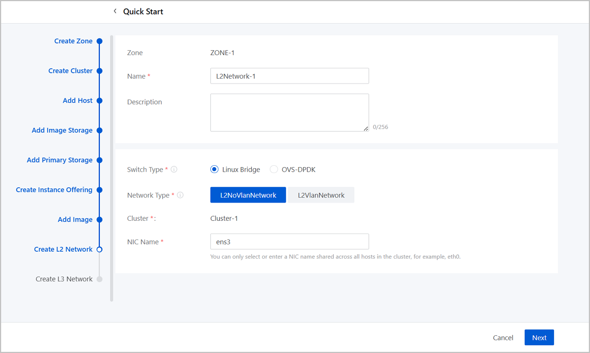
- Name: Enter a name for the L2 network.
- Description: Optional. Enter a description for the L2 network.
- Switch Type: Supported switch types include Linux Bridge and OVS-DPDK.
- Network Type: Choose a network type for the L2
network. Valid values: L2NoVlanNetwork, L2VlanNetwork.
- L2NoVlanNetwork
- If you do not need to use VLAN, select L2NoVlanNetwork.
- If you select L2NoVlanNetwork, the switch port connected by the specified NIC must be in the Access mode.
- L2VlanNetwork
- If you need to use VLAN on ZStack Cloud, select L2VlanNetwork.
- If you select L2VlanNetwork, the switch port connected by the specified NIC must be in the Trunk mode.
- VLAN ID: Enter a VLAN ID that matches the actual network configurations. Valid values: 1 to 4094.
- L2NoVlanNetwork
- Cluster: Display the the cluster to which the L2 network will be attached.
- NIC Name: Select or enter an NIC
name for the L2 network. For example, em01.Note: You can only select or
enter an NIC name shared across all hosts in the cluster.
Create an L3 Network
About this task
An L3 network includes IP ranges, gateway, DNS, and other network configurations that are used by VM instances.
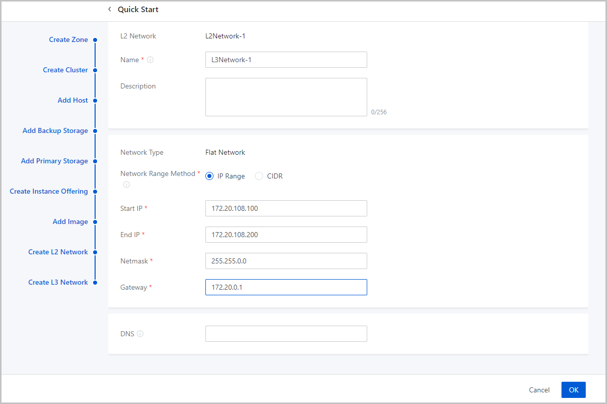
- Name: Enter a name for the L3 network.
- Description: Optional. Enter a description for the L3 network.
- Network Type: The wizard supports only flat network.
- Network Range Method: Select a method to add a
network range for the L3 network. You can select IP Range or CIDR.If you select IP Range, you need to set the following parameters:
- Start IP: Set a start IP address for the network range, for example, 172.20.108.100.
- End IP: Set an end IP address for the network range, for example, 172.20.108.200.
- Netmask: Set a netmask for the network range, for example, 255.255.0.0.
- Gateway: Set a gateway for the network range, for example, 172.20.0.1.
- DNS: Add a DNS server to provide domain name resolution services for the L3 network. You can specify 223.5.5.5, 8.8.8.8, or 114.114.114.114.
If you select CIDR, you need to set the following parameters:- CIDR: Set a CIDR block for the L3 network, for example, 192.168.108.1/24.
- Gateway: Set a gateway for the L3
network, for example, 192.168.108.1.Note:
- You can use the first or last IP address in the specified CIDR block as the gateway.
- If left blank, the first IP address in the specified CIDR block is used as the gateway.
- DNS: Add a DNS server to provide domain name resolution services for the L3 network. You can specify 223.5.5.5, 8.8.8.8, or 114.114.114.114.
What to do next
The wizard is completed.
Create a VM Instance
About this task
After you complete the initialization of ZStack Cloud, you can create a VM instance.Procedure
-
Create a VM instance.
On the main menu of ZStack Cloud, choose . Click the Fast Creation button on the right of Create VM Instance. Then, the Fast Creation page is displayed. On the Fast Creation tab page, set the following parameters:
- Name: Enter a name for the VM instance.
The name must be 1 to 128 characters in length and can contain Chinese characters, letters, digits, spaces, hyphens (-), underscores (_), periods (.), parenthesis (), colons (:), and plus signs (+) and cannot begin or end with spaces.
- Quantity: Enter the number of VM instances to be created. Valid values: 1 to 100. You can change the maximum number by modifying the value of Maximum VM Creation in Batch on UI in the global setting.
- Tag: Optional. Bind one or more tags to the VM instance as needed.
- Set the VM offering by using one of the following
methods:
Basic Offering: Set the VM offering by selecting an existing instance offering and disk offering.
Custom Offering: Set the VM offering by customizing VM configurations.
- Network Configurations: Configure the networks used by the VM instance. You can add multiple networks as needed.
- User Data: Optional. Inject user-defined parameters or scripts to customize configurations for the VM instance or to accomplish specific tasks.
Figure 1. Create VM Instance (Fast Creation) 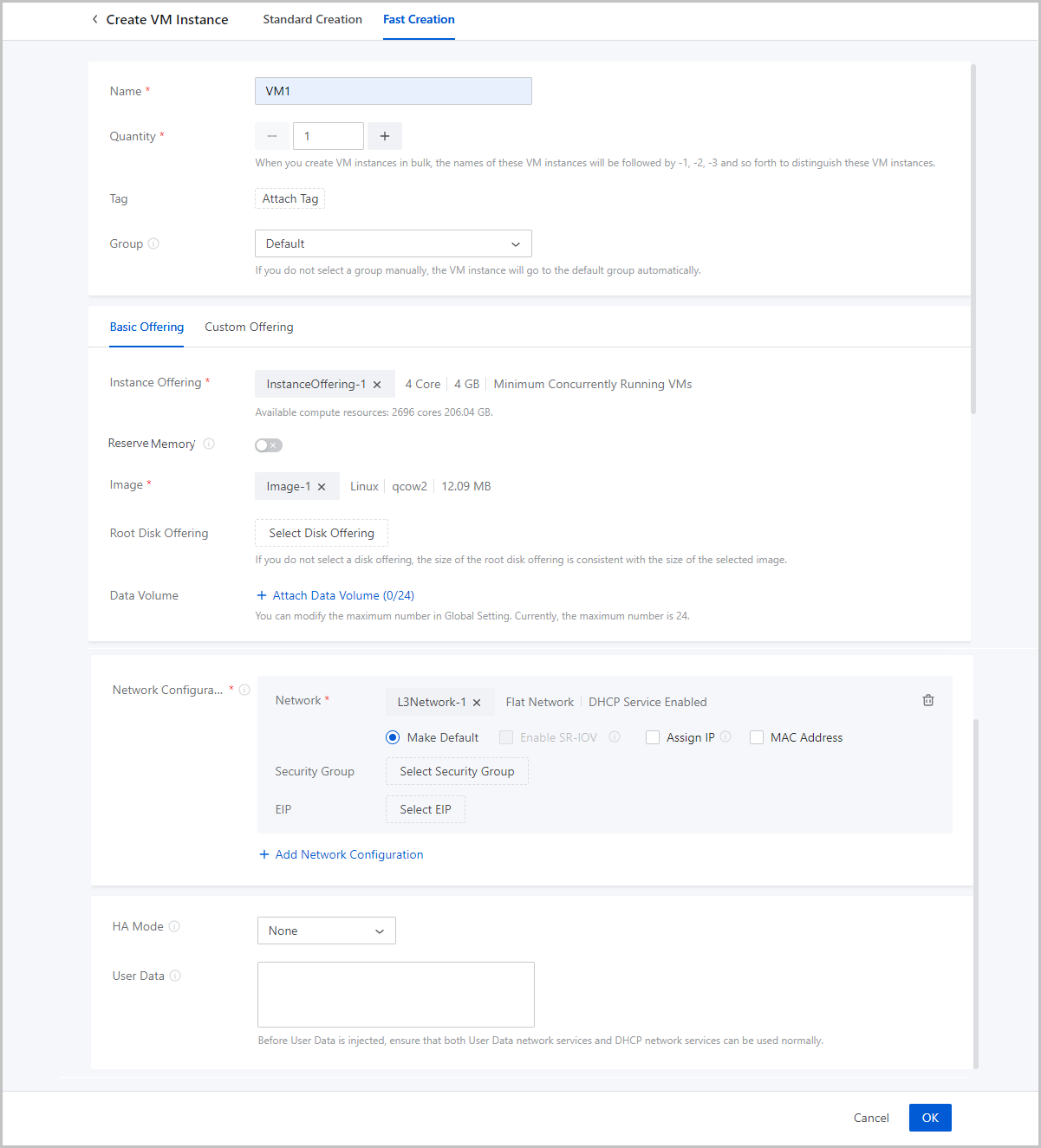
- Name: Enter a name for the VM instance.
-
Verify the VM instance.
After the VM instance is created, you can go to the console of the VM instance.
Figure 2. Open VM Console 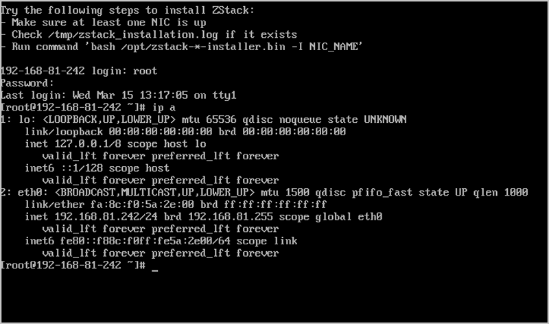
What to do next
You have completed the quick installation and usage of ZStack Cloud of the h84r edition. For more detailed information, see User Guide.