Network Virtualization
Overview
Network virtualization is a technology that abstracts network capabilities away from dedicated network hardware. The underlying hardware only needs to provide basic packet forwarding services. Network virtualization provides various network services, including data switching, routing, security groups, firewalls, and more, achieving an experience comparable to a physical network.
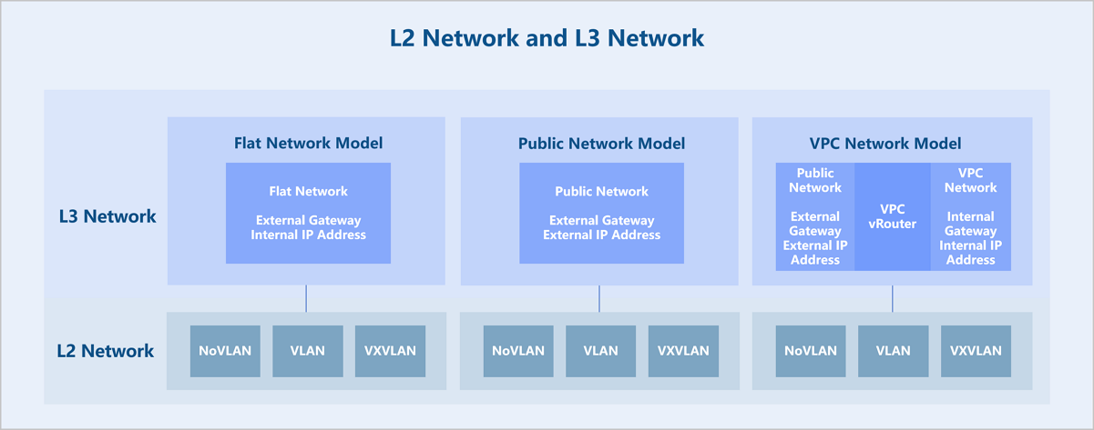
ZStack Cloud abstracts the network model into Layer 2 (L2) networks and Layer 3 (L3) networks. An L2 network is a layer 2 broadcast domain and offers layer 2 isolation. An L3 network primarily corresponds to network services from Layer 4 to Layer 7 of the OSI model. Technologies providing layer 2 isolation such as NoVLAN, VLAN, VXLAN, and SDN can serve as L2 networks. Creating an L2 network requires deploying corresponding virtual switches on all hosts in the cluster attached to the L2 network to provide a broadcast domain. Built on top of L2 networks, L3 networks come in several types: flat network, public network, and VPC network. Various network services based on L3 networks can be provided, such as DHCP, DNS, elastic IP (EIP), port forwarding, and load balancing.
Technical Features
L3 Networks
L3 networks include: flat network, public network, and VPC network.
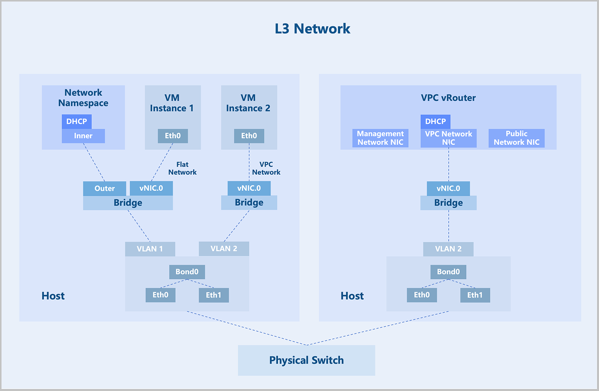
A flat network assigns private network addresses to VM instances, while allowing VM instances to access the public network through distributed elastic IPs (EIPs). Flat networks support network services such as DHCP, User Data, security groups, EIPs, and port mirroring.
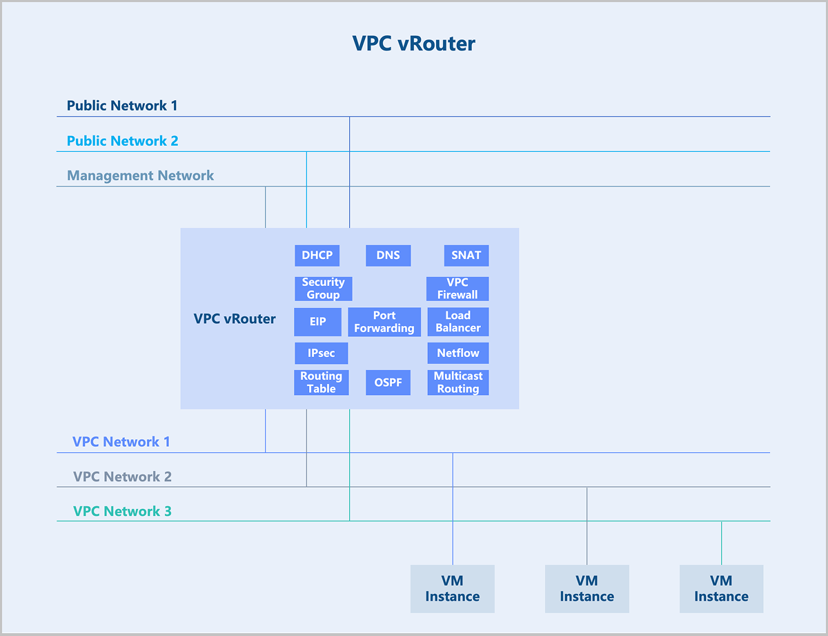
A VPC network is a customizable network space that enables tenants to build an isolated, self-managed virtual network within the cloud platform. It offers greater control over configuration and policy, enhancing the security of cloud resources. VPC vRouters provide VPC networks and their services. A single VPC vRouter can host multiple isolated VPC networks, providing VM instances with network services such as DHCP, DNS, SNAT, routing tables, security groups, VPC firewalls, EIPs, port forwarding, load balancing, IPsec, Netflow, OSPF and multicast routing.
VPC vRouter
A VPC vRouter is a dedicated VM instance running a customized Linux operating system and a management service agent. A single VPC vRouter can provide multiple isolated VPC networks. Each VPC vRouter contains a management service agent that receives commands from management nodes via the HTTP protocol to configure network services. VPC vRouters provide VM instances with network services including DHCP, DNS, SNAT, routing tables, security groups, VPC firewalls, EIPs, port forwarding, load balancing, IPsec, Netflow, OSPF, and multicast routing.
Security Group
In traditional data centers, networks divide into trusted zones, DMZ zones, and untrusted zones. Perimeter firewalls enforce traffic control to ensure network security. In virtualized data centers, perimeter firewalls may struggle to handle scenarios such as network isolation between different tenants and access control between different services within the same tenant flexibly. Therefore, ZStack Cloud introduces a new component: security group. A security group is a distributed firewall focused on controlling east-west traffic and supports inbound and outbound traffic control at the VM instance NIC level.
- The set of security group rules: supports the addition, deletion, and modification of rules to control rule actions.
- The set of associated NICs: supports the binding of VM instance NICs to apply security group rules to them.
- Default policies: If no rules are added, except communication between group members, the security group denies all inbound traffic by default, and allows all outbound traffic.
- Rule flexibility: Rules support on-demand modification, including source IP, destination IP, destination port, protocol type, and priority.
- Dynamic priority adjustment: When adding a rule, you can insert it at a specific priority. When removing a rule, priorities automatically adjust to remain consecutive.
- Multiple security groups per NIC: A VM instance NIC supports associating to multiple security groups. You can dynamically adjust the priority of these groups. By default, rules in the first-associated security group take effect first.
Technical Principles
- Composition of a security group:
- Source: Supports source data (for inbound direction) and destination data (for outbound direction).
- Address Type: Supports IPv4 and IPv6.
- Protocol Type and Port: Supports ICMP, TCP, UDP, and more.
- Action: Deny or allow.
- Priority of security group rules:
- Rule priority is a consecutive and unique (priority 0 indicates the highest priority by default). Lower priority numbers indicate higher precedence.
- By default, newly added rules have the lowest priority. When inserting a rule at a specified priority, subsequent rule priorities adjust automatically to ensure uniqueness.
- When traffic passes through a VM instance NIC, matching starts from the rule with the highest priority. If a match succeeds, the rule action executes. Otherwise, matching continues with the next rule.
- Import and export of security group rules:
- Existing rules support one-click export.
- Exported rules supports re-importing into other security groups with rule validation provided during import.
- Associating multiple security groups to a NIC:
- A VM instance NIC allows associating to multiple security groups. The associated groups support priority ordering. A lower number indicates a higher group priority.
- When traffic passes through the VM instance NIC, matching starts from the security group with the highest priority. If a rule within that group match succeeds, the rule action executes. Otherwise, matching proceeds to the next security group.
- NIC default policy:
- By default, the NIC's default inbound policy is Allow, and the default outbound policy is Deny. These default policies support modification.
- When traffic does not match any security group rule, the NIC's default policy executes.
Application Scenarios
- Access control among different services.Take a typical web application as an example.
- Allow any IP address to access TCP ports 80 and 443 on the Web VM instances.
- Allow the Web VM instances to access TCP port 8080 on the App VM instances.
- Allow the App VM instances to access TCP port 3306 on the DB VM instances.
Create separate security groups for the three business types (Web, App, DB) and configure corresponding rules to achieve access control among the different businesses.
Figure 1. Access Control Among Different businesses 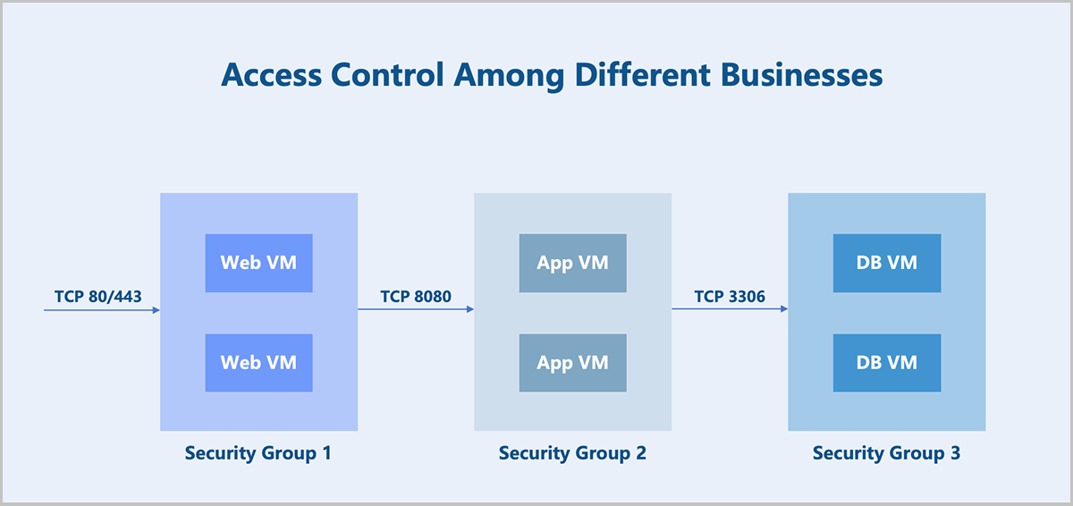
- Coexistence of multiple businesses.In addition to providing service capabilities, the above business VM instances also need to allow operational control (assumed to use the SSH protocol). There are two implementation options:
- Option 1: Add a new rule to each of the three security groups.
- Option 2: Create a new security group and associate it to the NICs of all the above business VM instances.
ZStack Cloud supports associating multiple security groups to a VM instance NIC. Option 2 is the preferred method for its better flexibility and controllability. You can configure two security groups for each business VM instance NIC mentioned above and adjust the security group priority and default rules as needed.
- Multi-level permission security configuration.In an IDC scenario, assume an administrator needs to prevent tenant VM instances from accessing certain external networks. There are two implementation options:
- Option 1: The administrator configures a default security group and rules for a project. The platform forces project members to associate this group when creating VM instances. From the project member's perspective, this security group is visible but cannot be disassociated.
- Option 2: The administrator configures a security group and rules for tenant VM instances. From the tenant's perspective, this security group is invisible and cannot be disassociated.
- Disabling communication within a security group.
By default, VM instances within the same security group can communicate with each other without any rule restrictions. In certain scenarios where communication between VM instances within the same group must be prohibited, you can disable the default rule: Allow for communication within the group. Note that this default rule cannot be deleted.
VPC Firewall
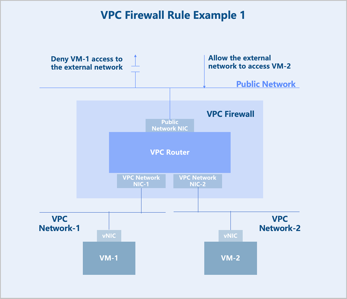
A VPC firewall controls north-south traffic within a VPC network. Based on iptables, VPC firewall rules deploy on the VPC vRouter. When you enable the VPC firewall for a VPC vRouter, ZStack Cloud automatically delivers a default rule (priority 10000) and system rules (priority 4000 to 9999) to the VPC vRouter. The default rule and system rules ensure mutual access between the VPC network and external networks by default.
The default rule supports modification only. System rules do not support modification, addition, or deletion, except disablement. After configuring custom rules, you can modify the default rule or disable system rules as needed. Before executing above operations, ensure that the custom rules meet expectations. Otherwise, your business may be affected.
You can configure custom rules on either the public network or the VPC network as needed.
Configure security rules between a VPC network and external networks on the public network. For example, to block VM instance-1 from accessing external networks and to allow external networks to access VM instance-2, configure the rules on the outbound direction of the public network.
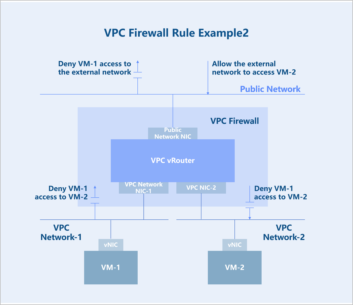
Configure security rules between VPC networks on the VPC network. For example, to block VPC network-1 from accessing VPC network-2, configure a deny rule on the inbound direction of VPC network-1 or on the outbound direction of VPC network-2.
Elastic IP
Typically, flat networks and public networks cannot communicate at layer 2 and cannot route to each other at layer 3. VM instances on a flat network cannot access the public network, and the public network cannot actively access VM instances on the flat network. To bridge the flat network and the public network, you need an elastic IP (EIP).
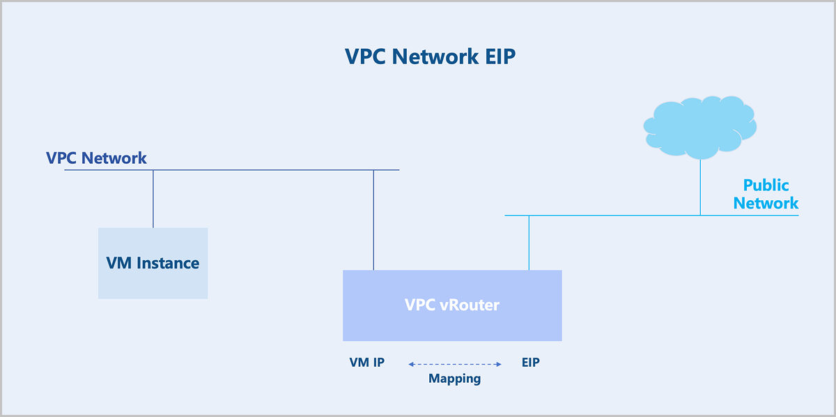
Similarly, VPC networks and public networks cannot communicate at layer 2 and cannot route to each other at layer 3. If you enable the SNAT functionality on the VPC vRouter, VM instances on the VPC network can access the public network, but the public network cannot actively access the VPC network. To bridge the VPC network and the public network, you need an EIP.
Technical Principles
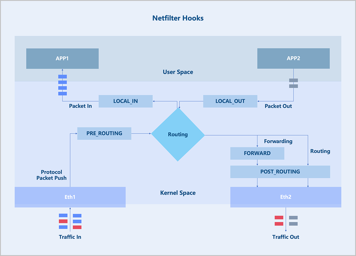
EIP applies the Linux Netfilter framework. Netfilter is a networking subsystem in the Linux kernel, which provides packet filtering, NAT, and other network-related Hook functions. Netfilter inserts a series of Hook points into the packet forwarding path. You can use the iptables tool to add rules at these Hook points to control how packets get forwarded.
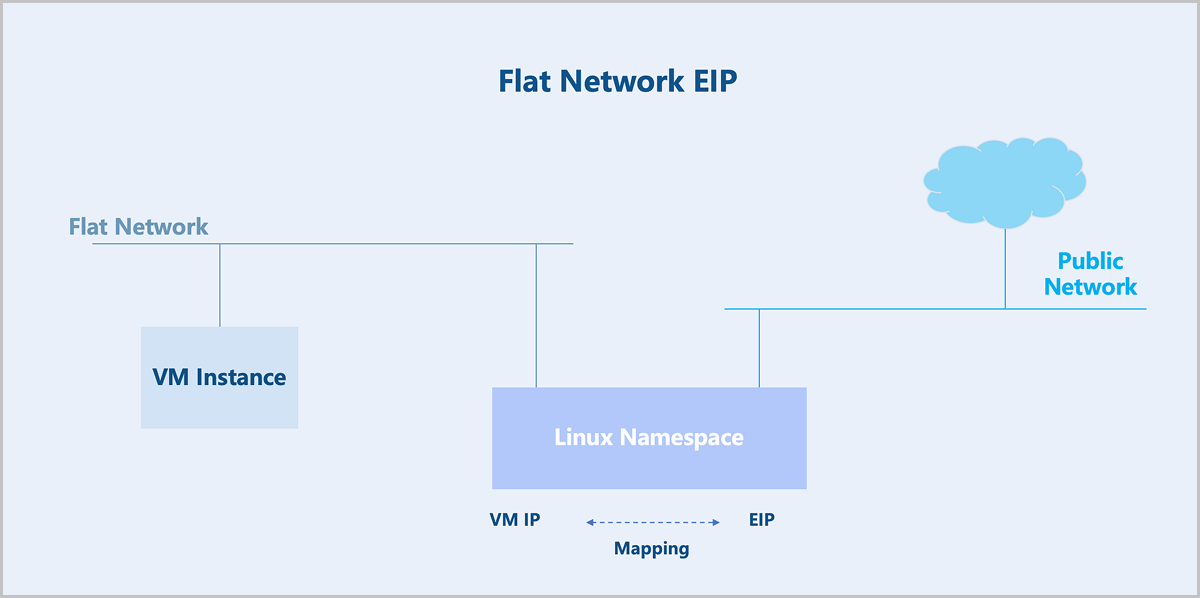
For flat networks, EIP is achieved through Linux Namespaces. You need to create a Linux Namespace on the underlying host of a VM instance. This Linux namespace maps the IP address of a VM instance to its EIP.
For VPC networks, EIP is achieved through the VPC vRouter. The VPC vRouter maps the IP address of a VM instance to its EIP without requiring creating a Linux Namespace.
Port Forwarding
Typically, flat networks and public networks cannot communicate at layer 2 and cannot route to each other at layer 3. VM instances on a flat network cannot access the public network, and the public network cannot actively access VM instances on the flat network. To bridge the flat network and the public network, you need an EIP. Flat networks do not provide port forwarding.
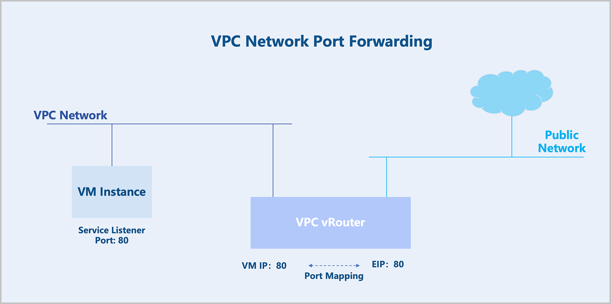
Similarly, VPC networks and public networks cannot communicate at layer 2 and cannot route to each other at layer 3. If you enable the SNAT functionality on the VPC vRouter, VM instances on the VPC network can access the public network, but the public network cannot actively access the VPC network. To bridge the VPC network and the public network, you need an EIP. If you want the public network to access specific ports on a VM instance, you can use port forwarding.
Technical Principles
Similar to EIP, port forwarding is achieved through the Linux Netfilter. Netfilter is a networking subsystem in the Linux kernel, which provides packet filtering, NAT, and other network-related hook functions. Netfilter inserts a series of Hook points into the packet forwarding path. You can use the iptables tool to add rules at these Hook points to control how packets get forwarded.
Flat networks do not provide port forwarding.
For VPC networks, port forwarding is achieved through the VPC router. Suppose you have a VM instance listening on TCP port 80, and want external users to access this service without exposing all other TCP ports on the VM instance. You can use port mapping. Port forwarding supports two mapping modes: one-to-one port mapping and port range mapping.
Load Balancing
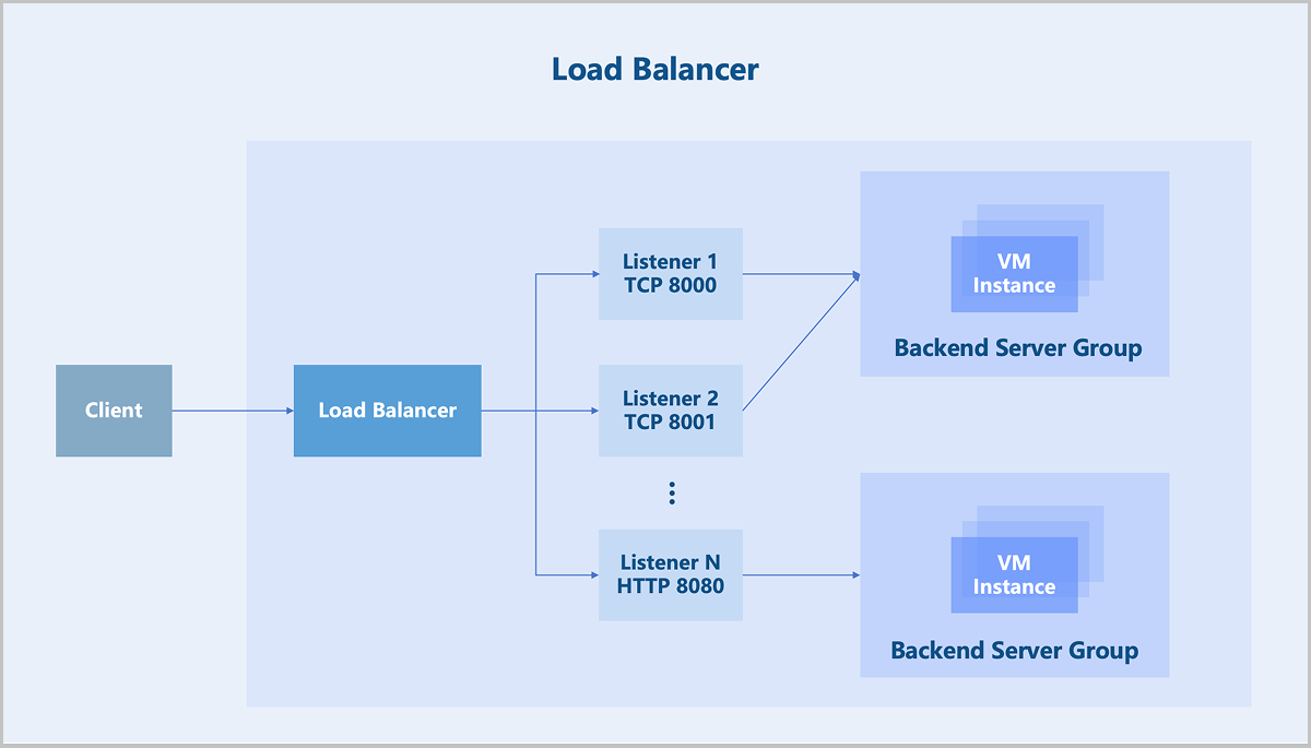
Load balancing employs various flexible algorithms to distribute all network requests evenly across backend server groups. Efficient traffic distribution reduces the load on individual servers to support high-traffic and high-concurrency accesses, meeting various business requirements.
- Round-robin algorithm: Forwards access requests to each backend server in turn. This algorithm is the simplest load balancing algorithm, which does not consider the established connections or system loads of backend servers and is mostly used when the performance of each backend server varies little.
- Weighted round-robin algorithm: Forwards access requests to backend servers based on the static weight configured in most cases according to hardware configurations of the servers. Requests are more likely to be distributed to backend servers with a higher weight. Weighted round robin is a variant of the round robin algorithm and is mostly used when the performance of each backend server varies much.
- Source IP hash: Generates a unique hash based on the source and destination IP addresses of the client requests and then forwards requests to specific backend servers. This algorithm is applicable to scenarios when the requests of different clients vary much.
- Least connections algorithm: Forwards new connection requests to backend servers recording least connections. This algorithm is applicable to scenarios when the time that backend servers used to handle different requests varies much. It is often used for long-term connection services.
- Layer 4 session persistence mechanism: A load balancer forwards all access requests from the same source IP address to a backend server.
- Layer 7 session persistence mechanism: The mechanism varies under different load balancing algorithms. The round-robin or weighted round-robin algorithm uses a cookie-based session persistence mechanism. The load balancer directs access requests to the previously recorded backend server through the Cookie. The source IP hash algorithm calculates the client source IP address using a hash function. Then all access requests from the same source IP address are forwarded to one backend server.
IPsec
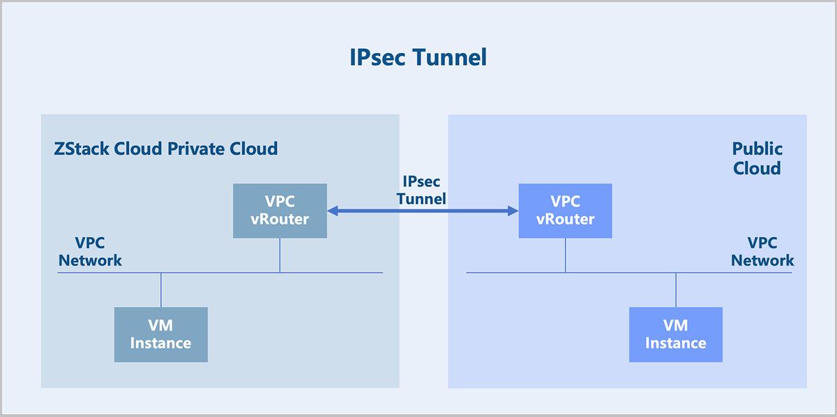
If you deploy ZStack Cloud in multiple regions, or both use a ZStack CloudPrivate Cloud and purchase Public Cloud services, you can connect these multi-cloud environments conveniently using an IPsec tunnel. It enables layer 3 communication between multi-cloud networks and ensures the confidentiality and security of data transmission between clouds.
- ESP protocol: Defines a secure transmission method for IP data. For more information, see ESP Protocol.
- IKE protocol: Defines a negotiation mechanism for generating keys used by ESP and keys used by IKE itself, as well as the authentication mechanism for IPsec. For more information, see IKE Protocol.
ESP Protocol
- Transport Mode
In this mode, typically only the payload of the IP packet is encrypted or authenticated. The unaltered or unencrypted original IP header preserves the original routing path. However, when using the authentication header (ESP Auth), the IP address cannot be modified through Network Address Translation (NAT) to avoid invalidating the hash value. The transport and application layers cannot be modified in any way, for example, by changing port numbers, as they are always secured via hashing.
Figure 2. Transport Mode-IP Packet 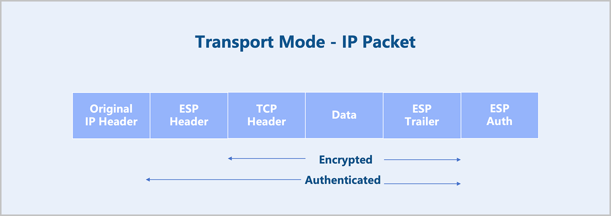
- Tunnel Mode
In this mode, the entire IP packet is encrypted and authenticated. It is encapsulated into a new IP packet with a new outer IP header attached. Tunnel mode is used to create virtual private networks for network-to-network communication (for example, connecting routers at different sites), host-to-network communication (for example, remote user access), and host-to-host communication. Tunnel mode supports NAT traversal.
Figure 3. Tunnel Mode-IP Packet 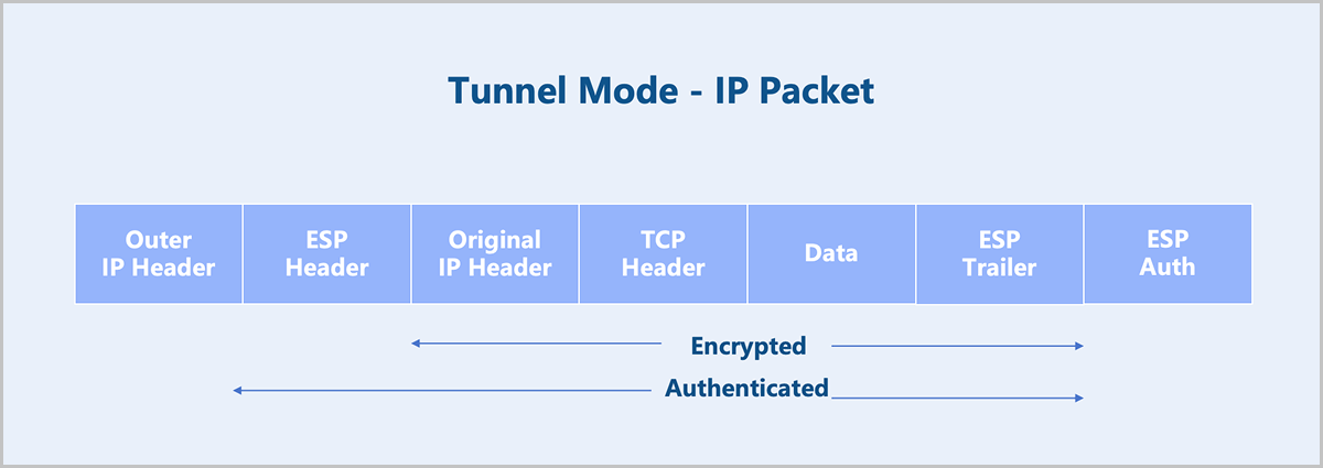
ZStack Cloud IPsec supports tunnel mode and does not support transport mode.
IKE Protocol
IKE has two versions: IKEv1 and IKEv2. We recommend to use IKEv2 for ZStack Cloud IPsec. IKEv2 can complete the negotiation of the IKEv2 SA and IPsec SA using four messages, simplifying the negotiation process compared to IKEv1.
- Initial Exchanges
- Create_Child_SA Exchange
- Informational Exchange
- The first message exchange completes the parameter negotiation for the IKE SA in plaintext. This includes negotiating encryption and algorithms authentication, exchanging ephemeral random numbers and performing a Diffie-Hellman (DH) exchange. Based on this, the key for encrypting subsequent IKE messages can be calculated.
Figure 4. Plaintext Exchange 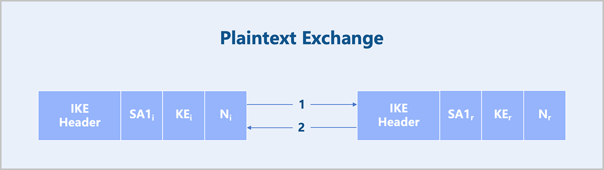
- The second message exchange completes identity authentication and IPsec SA parameter negotiation in encrypted form. IKEv2 supports three authentication methods: certificate authentication, pre-shared key (PSK), and EAP authentication. ZStack Cloud supports the PSK authentication method.
Figure 5. Encrypted Exchange (Based on PSK Authentication) 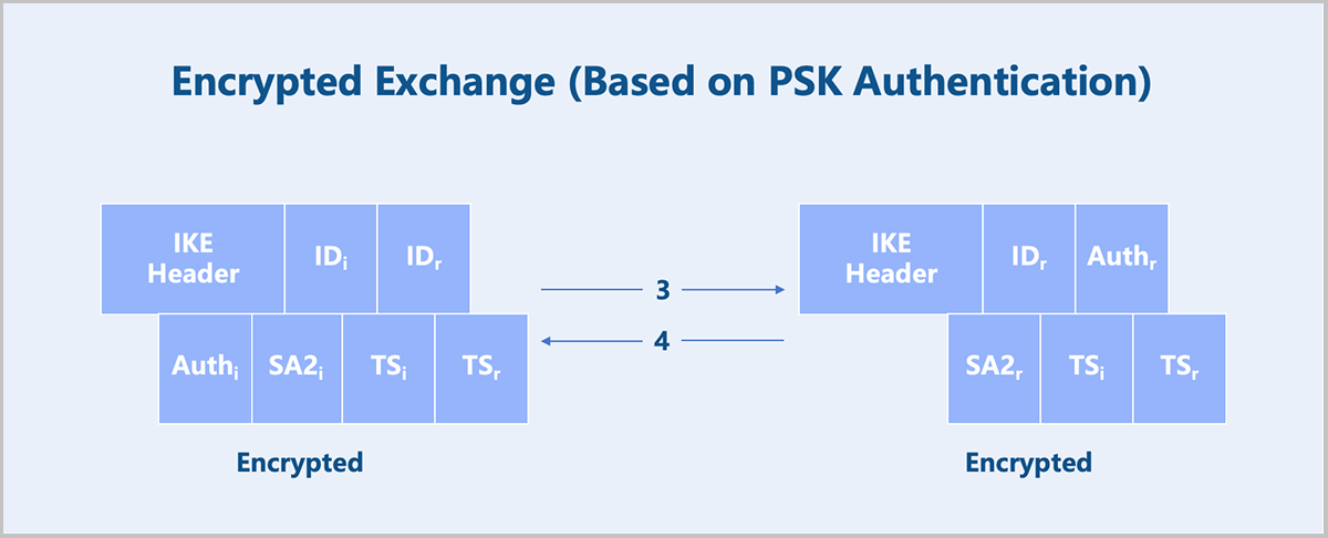
Port Mirroring
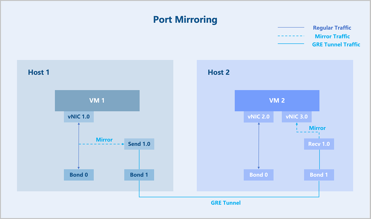
Port mirroring copies and forwards packets from a source port to a designated observation port. This allows data or traffic analysis to be performed on the second port or forwarded remotely for further inspection, minimizing impact on the original packet forwarding path.
The port through which the original packets pass is called the mirror port, also known as the monitored port. The second port that receives the copied data is called the observer port, also known as the collection port or monitoring port.
- Inbound: Only copies and forwards packets received by the mirror port.
- Outbound: Only copies and forwards packets sent from the mirror port.
- Both: Copies and forwards both inbound and outbound packets of the mirror port.
- Troubleshooting suspected attacks or network failures by capturing and analyzing packets from a specific port to identify threats or root causes.
- Monitoring and observing traffic on a port with minimal disruption to production traffic.
Technical Background
- Port: Copies packets received or sent by a specified port to the observer port. This type of mirroring is called port mirroring.
- VLAN: Copies packets received by all active interfaces in a specified VLAN to the observer port. This type of mirroring is called VLAN mirroring.
- MAC Address: Copies packets within a specified VLAN that match a designated source or destination MAC address to the observer port. This type of mirroring is called MAC mirroring.
- Packet Flow: Copies packet flows that match specified rules to the observer port. This type of mirroring is called flow mirroring.
ZStack Cloud emphasizes abstracting the physical location of user resources. Similar to the ERSPAN technology in physical switches, port mirroring on ZStack Cloud copies and forwards packets or traffic from a user's port to a device at any location (often using virtual resources, such as a VM instance) for remote detection and analysis.
Technical Principle
ZStack Cloud implements network virtualization based on the open-source Linux operating system. The corresponding port mirroring functionality is implemented using tools and libraries from the Linux ecosystem.
- Create another port on host 1: Send 1.0.
- Create a special network independent of the service network: the traffic network.
- Mirror the traffic from vNIC 1.0 to Send 1.0.
- Establish a GRE tunnel between Send 1.0 and Recv 1.0.
- The mirrored data is forwarded to VM instance 2 through the GRE tunnel.
Among these steps, flow mirroring is implemented using the Linux Traffic Control (TC) tool. The GRE tunnel operates on the independent traffic network, enabling packets and traffic to be copied and forwarded to any location within ZStack Cloud.
Netflow
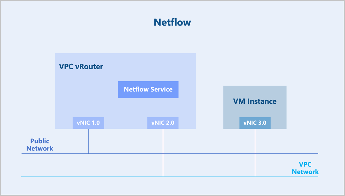
Netflow is a traffic statistics technology widely used in network traffic statistics, network planning, network security, and other fields. Netflow originated as a proprietary technology developed by Cisco and is now commonly supported by other network equipment vendors. The most widely used versions of Netflow are V5 and V9. For example, the IETF technical standard IPFIX (IP Flow Information Export) is based on the V9 version.
- Exporter: Runs on a network device and collects information about the network traffic received, forwarded, and sent by the current device.
- Collector: Receives Netflow information from exporters and stores this information.
- Analyzer: Performs traffic statistics based on the information from the collector, analyzing whether there is network congestion or traffic attacks.
In ZStack Cloud, the VPC vRouter can act as a Netflow exporter, sending Netflow information to a collector.
Technical Principle
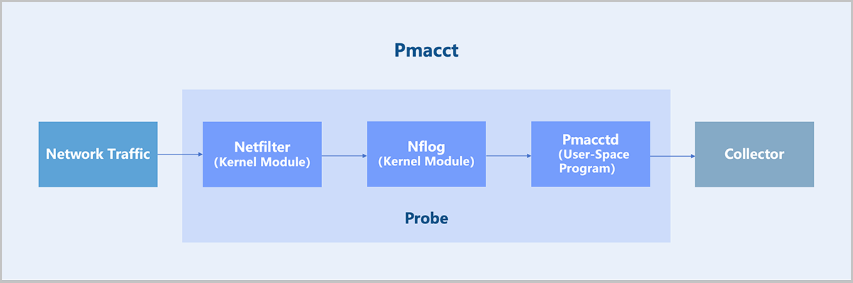
- Kernel Module: Adds iptables rules to direct traffic to the Nflog target. Example:
iptables -t raw -A VYATTA_CT_PREROUTING_HOOK -i eth1 -j NFLOG --nflog-group 2 # A line of network configuration automatically generated when each Netflow service is created. # eth1: The interface name of the corresponding network inside the VPC vRouter. # nflog-group 2: Specifies an NFLOG ID, which must match the iptables and Pmacctd configuration. - User-Space Program: The user-space program Pmacctd reads traffic data from the kernel via the NFLOG Netlink interface, then processes and converts it into Netflow format for export to a collector.
OSPF
| No. | Solution | Details |
|---|---|---|
| 1 | Static Routing |
|
| 2 | OSPF |
|
| 3 | Ingress Source-Aware Egress (Specific Scenario) |
|
This chapter focuses on the OSPF dynamic routing protocol.
Technical Principle
OSPF (Open Shortest Path First) is a link-state dynamic routing protocol developed by the IETF. OSPFv2 is used for IPv4 route synchronization, and OSPFv3 is used for IPv6 route synchronization. ZStack Cloud supports OSPFv2.
- RouterID
- The router ID is a 32-bit integer that uniquely identifies an OSPF router within the OSPF system.
- Area
- A large-scale network system may experience problems such as excessive routing information, long routing calculation times, and slow routing convergence. Any network change triggers route recalculations on every router, potentially causing route flapping. OSPF solves this problem by dividing the large network into multiple areas, each with an area ID.
- Based on LSA distribution, areas types include: standard area, Stub area, NSSA (Not-So-Stubby Area), and totally NSSA area.
-
Figure 1. Area 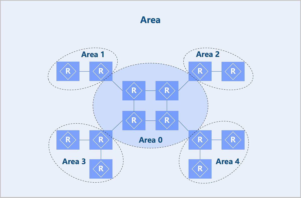
- Neighbor and Adjacency Relationships
- When OSPF protocol enables, a router periodically sends OSPF Hello packets out of its OSPF-enabled interfaces. A device that receives a Hello packet compares the parameters in the Hello packet with its interface parameters (for example, area ID). If the parameters match, a neighbor relationship forms.
- After forming a neighbor relationship, if the two devices successfully exchange Database Description (DD) packets and Link State Advertisement (LSA) packets, an adjacency relationship forms.
- Not all neighbors become adjacent.
- DR/BDR/DROther
- In broadcast or NBMA networks with multiple OSPF routers, not all pairs need to form adjacencies. Therefore, a DR (Designated Router) and a BDR (Backup Designated Router) are elected, while other routers are called DROther routers.
- Only when the DR, BDR, and all routers form adjacency relationships can OSPF packet exchange be reduced and route calculation accelerated.
- The DR and BDR are elected through an election algorithm. Election parameters include OSPF interface priority and Router ID. In practice, try to have physical routers elected as DR and BDR because VPC vRouters might be shut down due to operations from ZStack Cloud, which could cause network fluctuations throughout the data center.
-
Figure 2. Comparison Before and After Election 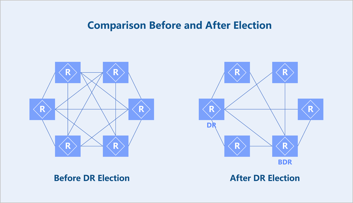
- LSA
- OSPF is a protocol that calculates routing information based on network topology information. LSAs are used to describe the network topology state.
LSA Type Description Type 1 Each OSPF router generates a Type 1 LSA, which describes the device's link states and costs. It is propagated within its area. Type 2 Generated by the DR, it describes the OSPF routers connected to a broadcast network and is propagated within its area. Type 3 Generated by an ABR (Area Border Router), it publishes routes for network segments within an area to other areas. Type 4 Generated by an ABR, it describes the route to an ASBR (Autonomous System Boundary Router). Type 5 ASBRs generate and advertise external routes into the relevant OSPF areas.
- OSPF is a protocol that calculates routing information based on network topology information. LSAs are used to describe the network topology state.
Multicast
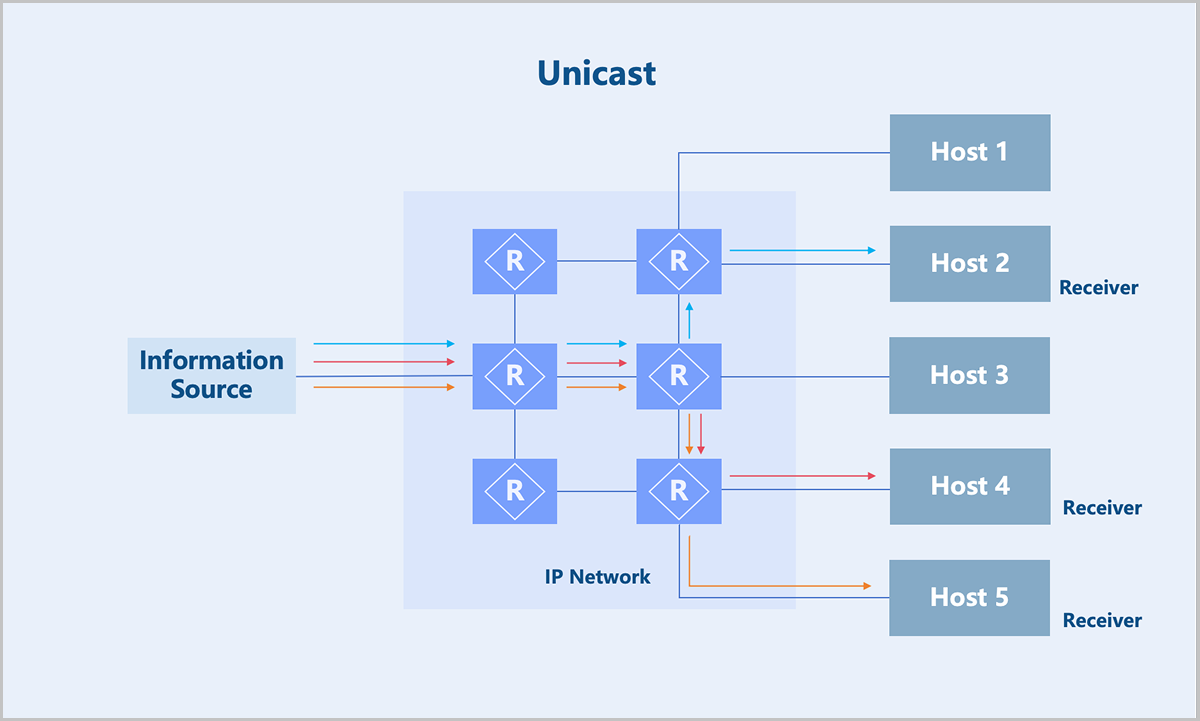
- Unicast: The source sends a separate data copy to every recipient. Drawback: Numerous recipient impose high load and network bandwidth demands on the source.
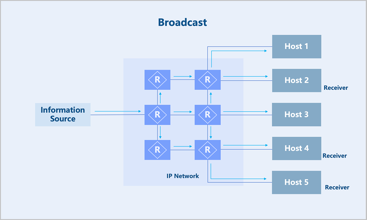
- Broadcast: The source sends a piece of broadcast data, and the switch replicates the data. Drawback: Cannot cross layer 3 boundaries. The exposure of data to non-intended recipients cause information security risks and wasting bandwidth.
- Multicast: The source sends only a piece of the data. Replication and distribution of the data occur at network nodes as far from the source as possible. Compared to unicast and broadcast, multicast uses bandwidth more efficiently, reduces network load, and enhances data transmission security.
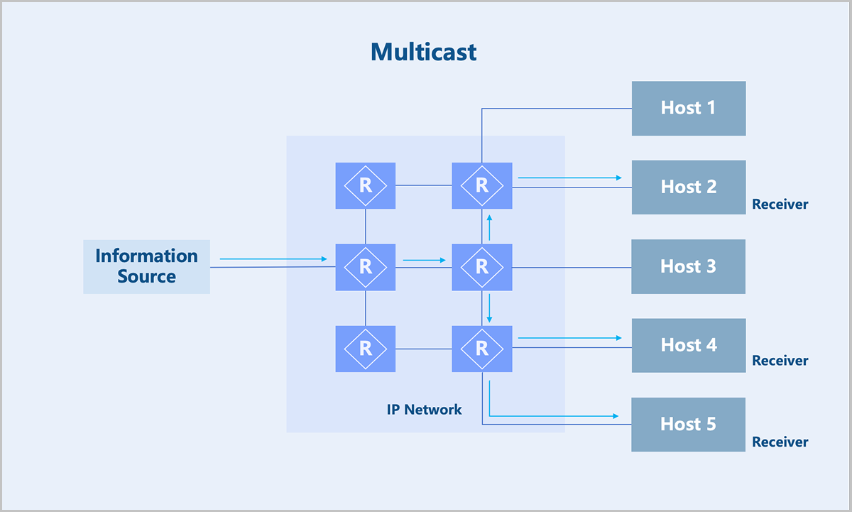
Therefore, multicast technology effectively solves the problem of single-point transmission and multi-point reception. This technology is widely used in fields with high demands for bandwidth and real-time data interaction, such as internet TV, live streaming, distance education, telemedicine, and real-time video conferences.
- Identifying a multicast group. See Multicast Address.
- Joining in and leaving from a multicast group. See Multicast Members Management.
- Forwarding path of a multicast packet: multicast distribution tree. See Multicast Distribution Tree.
- Establishing a forwarding path between multicast senders and receivers. See Multicast Routing Protocol.
Multicast Address
| Range | Purpose |
|---|---|
| 224.0.0.0 to 224.0.0.255 | Reserved addresses. For example, OSPF uses 224.0.0.5 and VRRP uses 224.0.0.18. |
| 224.0.1.0 to 238.255.255.255 | Multicast addresses available for user applications. |
| 239.0.0.0 to 239.255.255.255 | Local multicast addresses. |
Multicast Members Management
You can maintain the relationship between multicast groups and multicast recipients on switches and routers via multicast registration protocols.
- IGMPv1: Standardizes the basic process of querying and reporting for group members.
- IGMPv2: Adds mechanisms such as rapid departure of group members.
- IGMPv3: Adds support for the SSM model.
Multicast Distribution Tree
- Shortest Path Tree (SPT): A distribution tree rooted at the multicast source. The network must establish a tree for every multicast source sending packets to the group, resulting in a very large routing table scale. SPT is applicable to both PIM-DM and PIM-SM networks.
- Root Path Tree (RPT): A distribution tree rooted at a specific router, known as the Rendezvous Point (RP), formed by the shortest paths from the RP to all receivers. For each multicast group, the network maintains only one tree. The multicast source first sends data packets to the RP, and then forwarded the packets along the shared tree to all receivers. RPT is applicable to PIM-SM networks.
Multicast Routing Protocol
A commonly used multicast routing protocol is the PIM protocol. The PIM protocol operates in three modes: PIM-DM, PIM-SM, and PIM-SSM mode.
QoS
QoS (Quality of Service) involves bandwidth management and quality assurance. In modern network environments, QoS is key to ensuring network efficiency and performance. Effective bandwidth control optimizes resource allocation and improves user experience, which is particularly important in multimedia transmission and enterprise-level applications.
- NIC QoS: Provides QoS configurations, such as dedicated bandwidth resources and rate limiting for a specified NIC.
- VIP QoS: Supports configuring QoS for a specified Virtual IP (VIP), providing bandwidth resources and rate limiting for NICs using that VIP. You can configure multiple QoS rules for different ports of a single VIP.
- Shared Bandwidth: Shared Bandwidth is a QoS service available for multiple VIPs. VIPs added to the same shared bandwidth share the same bandwidth resources and are rate-limited collectively. Currently, the shared bandwidth of ZStack Cloud is only available for public network VIPs. A public network VIP is the primary entrance for VM instances in a VPC network to access the public network. For example, an EIP created based on a public network VIP and associated with a VPC VM instance's NIC allows that VM instance to communicate with the public network via the VIP. If multiple VM instances use VIPs that belong to the same shared bandwidth, these VM instances share the same bandwidth resources and are collectively rate-limited when accessing the public network, providing an effective way to save public network access costs.
Figure 1. Shared Bandwidth 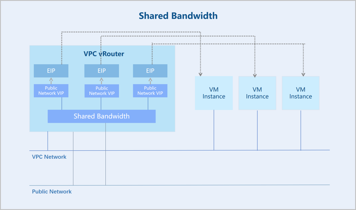
- qdisc (Queueing Discipline): Determines packet handling policies on a network interface, enabling operations such as queuing, dropping, reordering, or remarking of packets.
- class (Traffic Class): In classification-supported qdiscs, traffic can be divided into different classes. Each class can have its own queuing discipline and bandwidth limits.
- filter: Classifies data flows and determines the class of a packet. Filters can classify data flows based on various criteria such as port numbers and IP addresses.
- Define qdiscs and classes based on the specified QoS policy:
- Define a root qdisc, typically HTB (Hierarchical Token Bucket), to create a hierarchical bandwidth management structure.
- Create classes under the qdisc. Each class represents a different traffic policy. Configure bandwidth limits for each class.
- Configure filters: Configure filters for the classes based on the specified QoS policy. Ensure that traffic is correctly classified into the corresponding classes.
- Monitoring and adjustment: Monitor the traffic and classes using the tc commands. Adjusts bandwidth allocation and policies based on monitoring results to maintain network performance and responsiveness.