Introduction
About This Guide
Intended Audience
This guide is intended for experienced administrators who want to install ZStack ZSphere.
Installation Modes
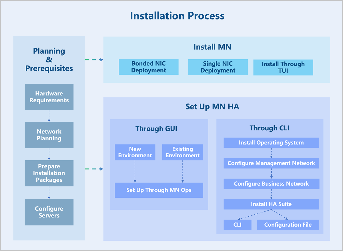
ZStack ZSphere provides three installation modes. Each includes different components and is intended for different scenarios.
| Installation Mode | Component | Scenario |
|---|---|---|
| Management Node Mode |
|
Suitable for installing the management node. |
| Compute Node Mode |
|
Suitable for installation as nodes other than the management node, for example:
|
| Expert Mode | Base operating system |
Planning and Prerequisites
Hardware Requirements
- For demonstration environment: The server must have at least 4 CPU cores and 8 GB of memory.
- For production environment:
- Management node configuration: For small-scale scenarios, the server must have at least 8 CPU cores, 16 GB of memory, and 240 GB of storage.
The actual hardware configuration requirements depend on your business scale. For details, contact official technical support.
- Compute node configuration: The actual hardware configuration requirements depend on your business scale. For details, contact official technical support.
- Management node configuration: For small-scale scenarios, the server must have at least 8 CPU cores, 16 GB of memory, and 240 GB of storage.
Recommended Hardware Configuration
| Device | Configuration | |
|---|---|---|
| Server | CPU |
|
| Memory | No special requirements. DDR4 or higher specification memory is recommended. | |
| Motherboard | Standard dual-socket server motherboard. | |
| RAID Controller | Supports SAS/SATA RAID 0/1/10 and passthrough mode. | |
| Disk | No special requirements. Select HDD or SSD based on capacity and performance requirements. | |
| Network Ports |
|
|
| Network Switch |
|
|
Hardware Planning
You need to plan your server resources according to your production needs. In a large data center with sufficient resources, we recommend deploying two servers as management nodes to control the entire virtualization platform. These two management nodes provide high availability. If one management node fails, the system automatically triggers a high availability switchover within seconds. This ensures the management service remains continuously available. In a small data center, you can use a single server as the management node.
The remaining servers act as compute nodes. In a large data center, you can select multiple compute nodes to act as image storage. This expands the total image storage capacity and improves throughput. In a small data center, the image storage can share a server with the management node.
Network Planning
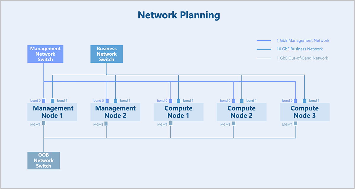
- The management network uses dual Gigabit networks for managing hardware resources related to the virtualization platform. The business network uses dual 10-Gigabit networks for virtual machine service traffic. You can configure network speeds based on your actual business requirements.
- If you use network storage such as NFS or distributed storage, you need also plan an additional storage network to handle storage traffic.
- We recommend that you maintain consistent NIC naming across all servers and use NICs with the same name to carry the same type of network traffic. For example, all management network traffic use the
em1NICs. - If you use a VLAN network, you need to configure the corresponding VLAN network communication on the switch in advance.
- ZStack ZSphere automatically assigns IP addresses to virtual machines. You need to reserve an IP range that does not conflict with the system and ensure this range does not conflict with any existing DHCP services in your network environment.
Prepare Installation Packages
ZStack ZSphere ISO is built on Helix, a self-made virtualization kernel software that operates between the infrastructure layer and the upper-layer operating systems. It integrates essential components like hardware drivers, macro kernels, and virtual agents, shielding the differences among heterogeneous hardware. This releases operating systems from hardware driver dependencies, ensuring proper access to the heterogeneous hardware on the under layer. By doing so, Helix enhances hardware compatibility, high reliability, high availability, scalability, and performance of your virtual environment.
You can install ZStack ZSphere without connecting to the public network or configuring a yum source, allowing for a completely offline installation.
| Sever Architecture | Package Name |
|---|---|
| x86 | ZStack-ZSphere-x86_64-DVD-5.0.3-H84r.iso |
| ZStack-ZSphere-x86_64-DVD-5.0.3-KylinV10SP3.iso | |
| ARM | ZStack-ZSphere-aarch64-DVD-5.0.3-H22e.iso |
| ZStack-ZSphere-aarch64-DVD-5.0.3-KylinV10SP3.iso |
 Note: After obtaining the software package, use an MD5 checksum tool to verify the checksum and ensure the software is complete and intact.
Burn ISO Image Using Rufus
After you obtain the ISO package, you can use Rufus to burn the ISO image to a USB drive.
Procedure
-
Select an ISO image.
- Connect your USB drive and open Rufus.
- In the Boot Selection drop-down list, choose Disk or ISO image.
- Click SELECT to open the ISO image file that you obtained.
图 1. Select ISO Image 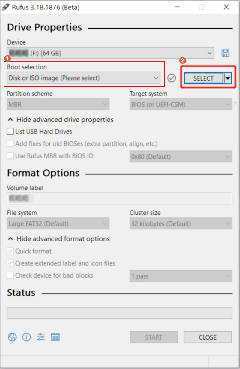
-
Burn the image.
-
Confirm the warning message.
Note: Burning the image will format the data on
the USB drive. If you have important data on your USB drive, make
sure to back it up before formatting.
图 2. Burn the Image 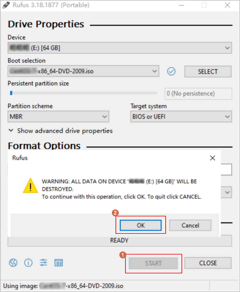
-
Confirm the warning message.
What to do next
After the burning process completes, you can use the USB drive as a boot disk. ZStack-ZSphere supports booting in Legacy mode or UEFI mode.Burn ISO Image Using Fedora Media Writer
After you obtain the ISO package, if you are using the Kylin operating system, we recommend using Fedora Media Writer to burn the ISO image.
Procedure
-
Select an ISO image.
- Connect your USB drive and open Fedora Media Writer.
- Click Custom Image to open the ISO image file that you obtained.
-
Burn the image.
-
After selecting the ISO image, keep the other options at their default
settings and click Write Disk.
Note: Burning the image will format the data on
the USB drive. If you have important data on your USB drive, make
sure to back it up before formatting.
-
After selecting the ISO image, keep the other options at their default
settings and click Write Disk.
What to do next
After the burning process completes, you can use the USB drive as a boot disk. ZStack-ZSphere supports booting in Legacy mode or UEFI mode.Configure Servers
- The installation process overwrites all data, so confirm that you have backed up all disks in the servers.
- Enter the server BIOS and enable CPU VT and Hyper-Threading (HT) options.
- Configure the appropriate RAID level in the RAID controller to provide data redundancy.
- Set the USB drive as the first boot device.
Install ZStack ZSphere
Install Management Node
Bonded NIC Deployment
To meet the requirements for network port bandwidth capacity and high reliability, NIC bonding must be configured in production environments. Since the operating system installation process is identical for both x86 and ARM servers, this chapter uses x86 servers to introduce the detailed installation procedure.
Procedure
-
Select the boot option.
Enter the ISO boot interface and choose the default option to start the operating system installation. You can select based on your actual situation, but we recommend using the graphical user interface (GUI) for installation. If the server does not have a VGA port and only supports serial connections, you can use either VNC or text mode installation methods.
- GUI method
- VNC method
- Text mode method
图 1. System Boot 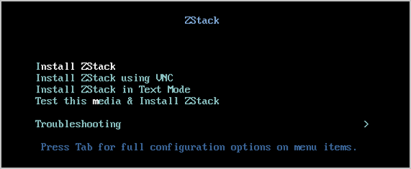
-
Review the installation configuration summary.
This page displays the system installation configuration. You can modify the configuration as needed. By default, ZStack ZSphere is configured with the following settings:
- Keyboard: English (US)
- Language Support: English (United States)
- Time & Date: Asia/Shanghai (UTC+8). We recommend that you check the host's time in advance and configure it to the current time and time zone.
图 2. System Installation Interface 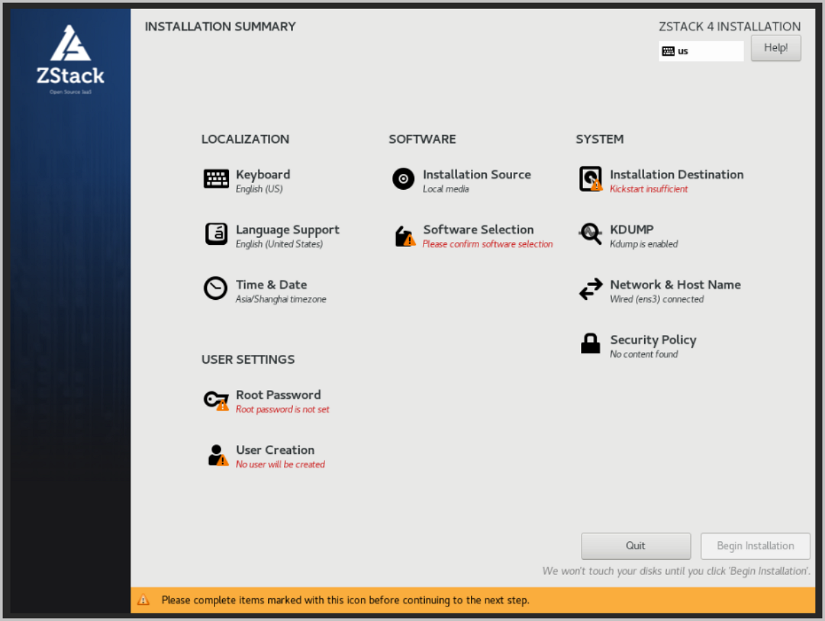
-
Select the installation mode.
图 3. Select Installation Mode 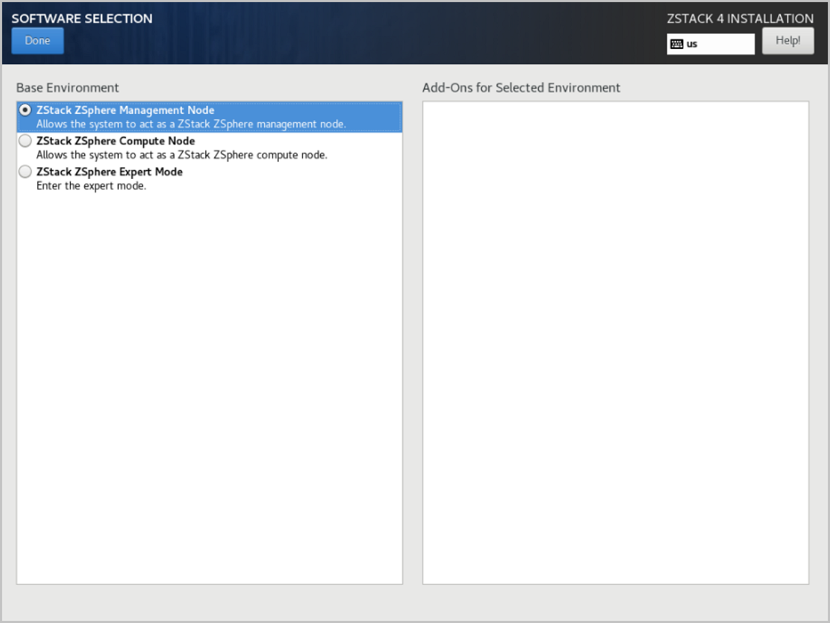
-
Configure the disk partitions.
-
For Storage Configuration, we recommend selecting
Automatic to automatically configure the disk
partitions.
If you need to manually configure disk partitions, refer to the following guidelines based on the BIOS boot mode:
- UEFI Mode:
- /boot: This directory stores the core files needed for Linux boot. We recommend allocating 1 GB of space.
- /boot/efi: This directory stores the UEFI boot files. We recommend allocating 500 MB.
- swap: This is the swap area. We recommend allocating 32 GB.
- /: This is the root directory for the Linux system. We recommend allocating all remaining space.
- Legacy Mode:
- /boot: This directory stores the core files needed for Linux boot. We recommend allocating 1 GB of space.
- swap: This is the swap area. We recommend allocating 32 GB.
- /: This is the root directory for the Linux system. We recommend allocating all remaining space.
Note:
- The above values represent the recommended partition sizes for ZStack ZSphere (total disk capacity should be greater than 300 GB).
- In Legacy mode, if the system disk capacity exceeds 2 TB, you need to configure a BIOS boot partition to support GPT partitioning. UEFI mode does not have this limitation and supports GPT partitioning.
- UEFI Mode:
图 4. Configure Disk Partitions 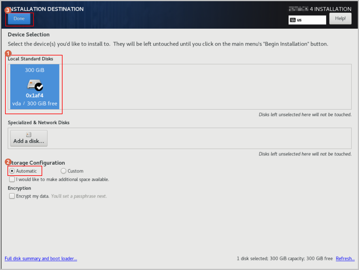
-
For Storage Configuration, we recommend selecting
Automatic to automatically configure the disk
partitions.
-
Add a bond device.
- On the INSTALLATION SUMMARY page, click Network & Host Name.
- On the NETWORK & HOST NAME page, click the + button at the bottom left of the page. This will open the Add device dialog. From the drop-down list, choose Bond, then click Add.
图 5. Add Bond Device 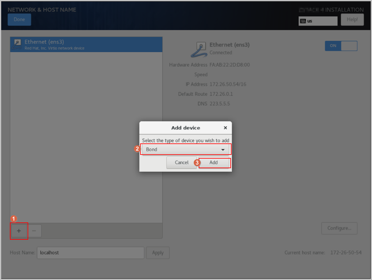
-
Add a Bond Slave.
-
In the Bond configuration dialog, adjust the Connection name as needed.
Note: Make sure the Connection name matches the Interface name.
图 6. Adjust Connection Name 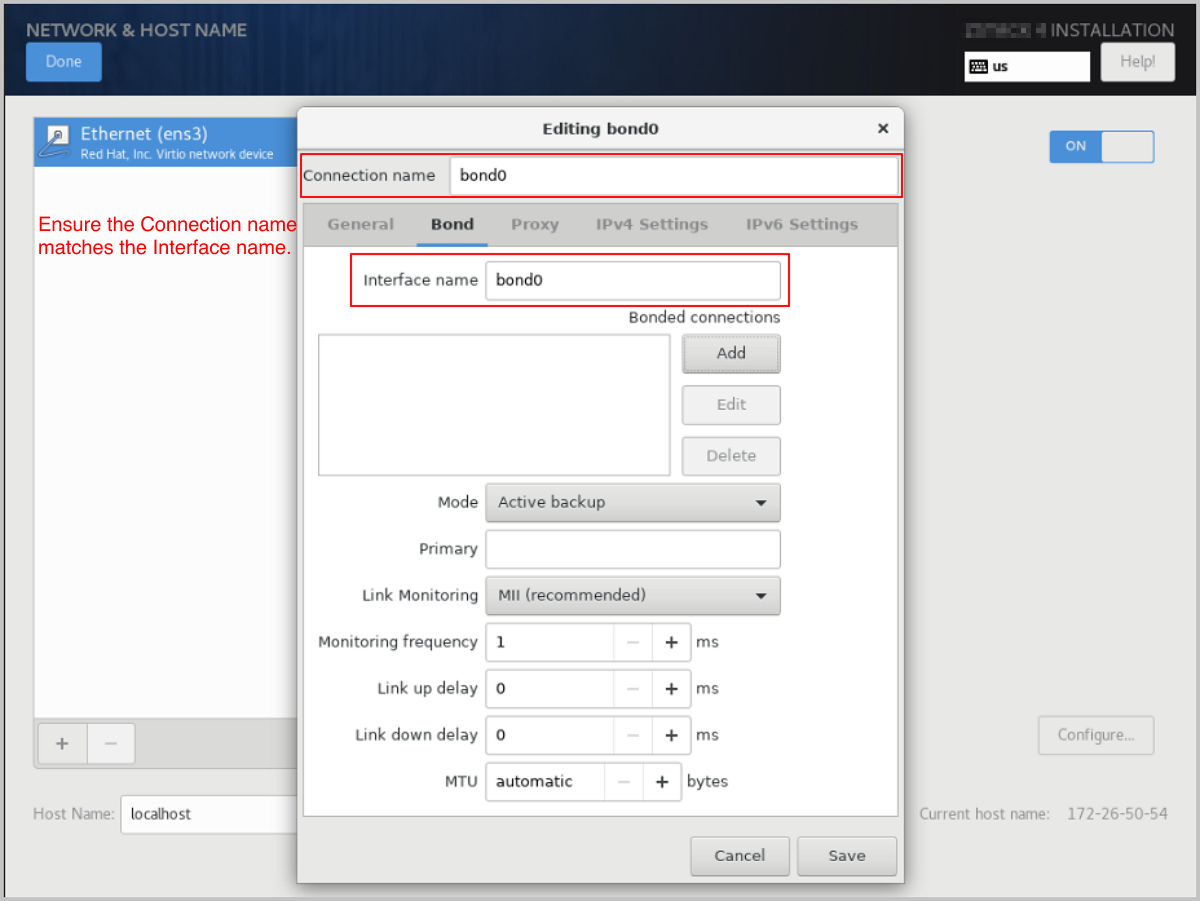
-
On the Bond configuration window, click Add to
add a bond slave.
图 7. Add Bond Slave 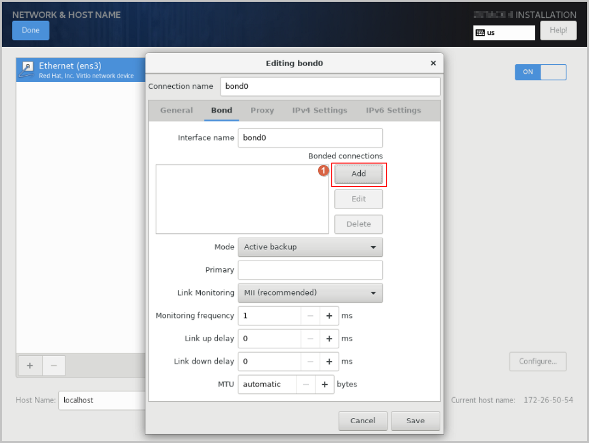
-
In the Choose a Connection Type dialog, choose a
connection type from the drop-down list, such as
Ethernet, and then click
Create....
图 8. Select Bond Slave Connection Type 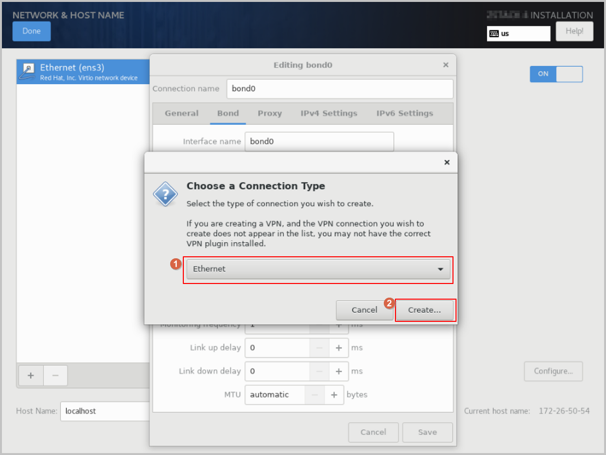
-
On the Ethernet tab of the Editing bond0
slave1 dialog, click Device and
select the Slave device you want to bind, such as ens3
(corresponding MAC address). Keep the other options as
default or customize them as needed, then click
Save.
图 9. Select Bond Slave Device 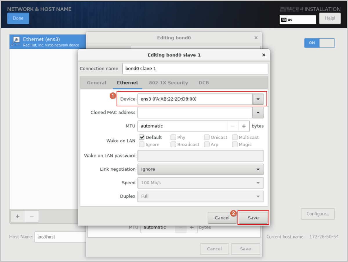
-
In the Bond configuration dialog, adjust the Connection name as needed.
-
Select the Bond mode.
In the Bond configuration dialog, choose the bond mode from the Mode drop-down list as needed, such as Active backup. Keep the other options as default or customize them as needed, then click Save.
图 10. Select Bond Mode 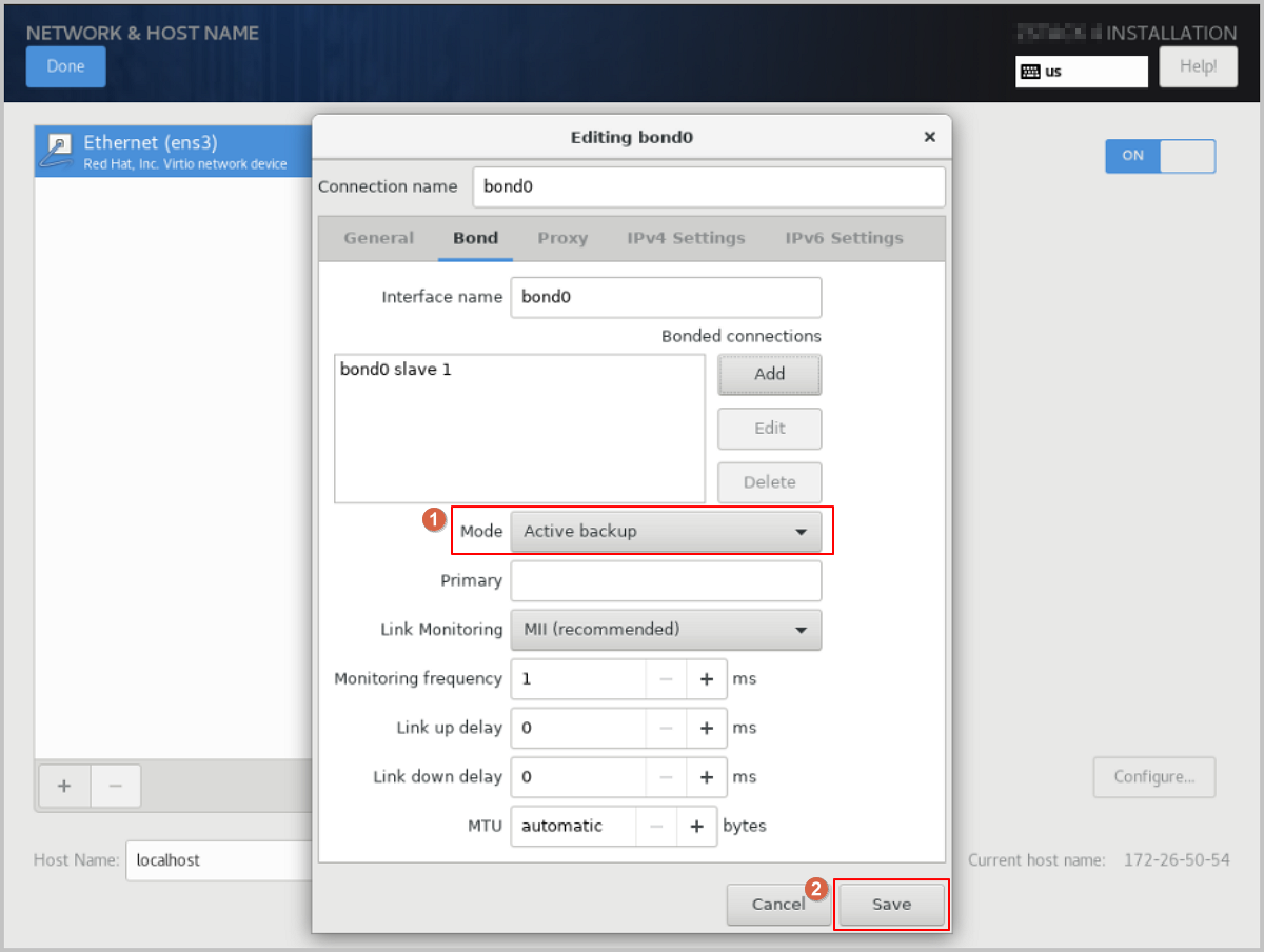
-
Disable IPv4 on the original NIC.
-
Select the original NIC, such as Ethernet
(ens3), and click Configure.
图 11. Configure Original NIC 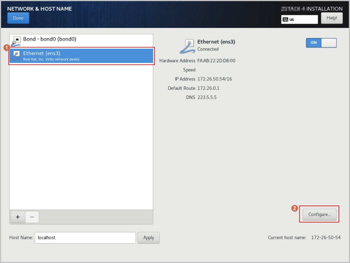
-
The Editing ens3 dialog pops up. Click
IPv4 Settings to access the IPv4
Settings tab. Change the Method
parameter value to Disabled, then click
Save.
图 12. Disable IPv4 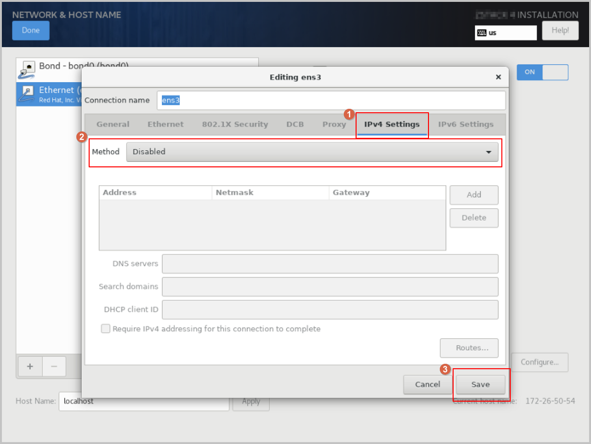
-
Select the original NIC, such as Ethernet
(ens3), and click Configure.
-
Configure a static IP address for Bond.
-
The Editing bond0 dialog pops up. click
IPv4 Settings to access the IPv4
Settings tab. Change the Method
parameter value to Manual to switch the IP
address acquisition method to manual.
Note: You can configure the IP address acquisition method as needed,
including using DHCP for automatic acquisition or specifying it
manually.
图 13. Configure Bond Static IP Address 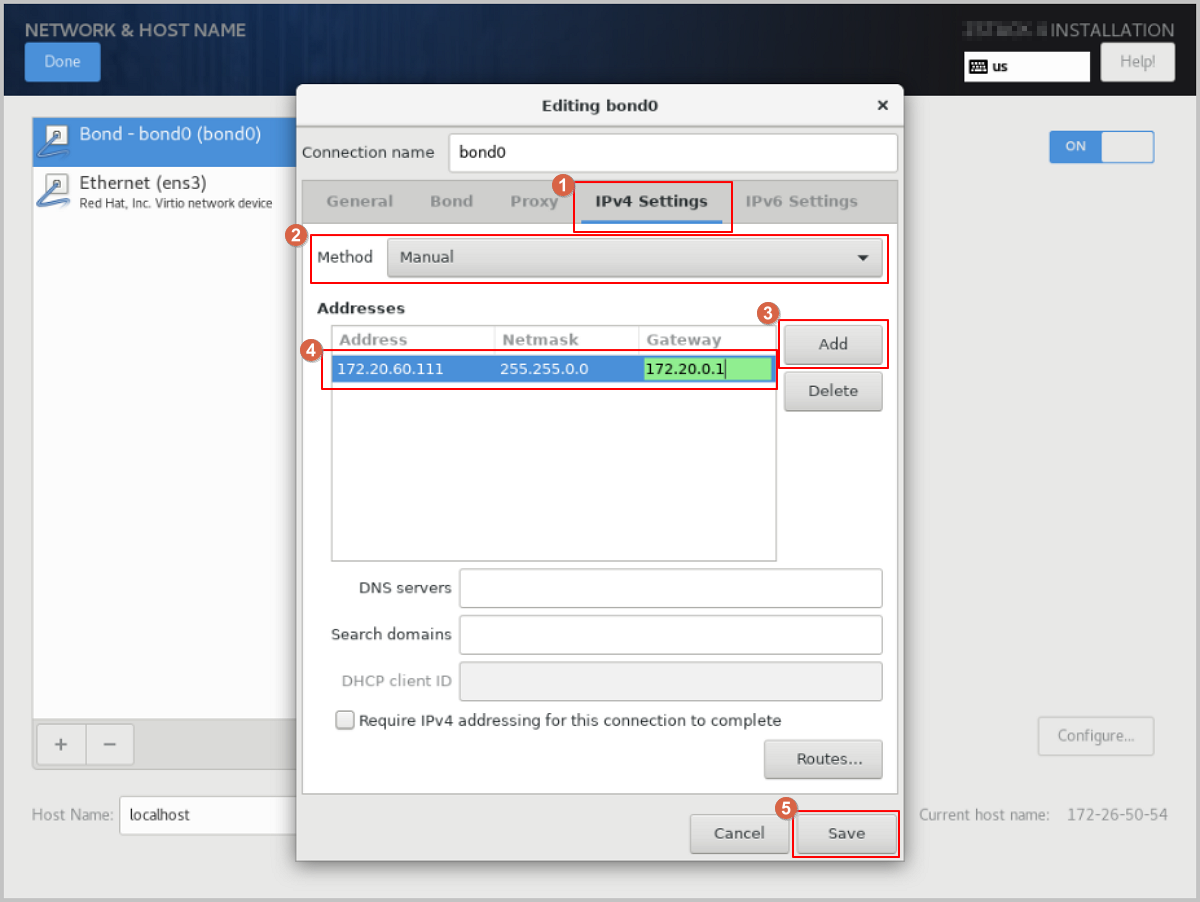
-
The Editing bond0 dialog pops up. click
IPv4 Settings to access the IPv4
Settings tab. Change the Method
parameter value to Manual to switch the IP
address acquisition method to manual.
-
Configure the NIC to activate automatically.
In the Editing bond0 dialog, click General to access the General tab. Select the Connect automatically with priority checkbox to set the NIC to activate automatically, then click Save.
图 14. Configure NIC to Activate Automatically 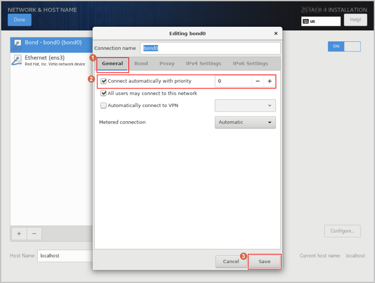
-
Complete the Bond configuration.
- Check the Bond configuration settings. Ensure that On is enabled and that you have configured the IP address. Also, make sure the Bond Slave (such as ens3) is set to On. Otherwise, ZStack ZSphere will not be installed properly.
- Review the configuration and click Done to return to the INSTALLATION SUMMARY page.
图 15. Check Bond Configuration 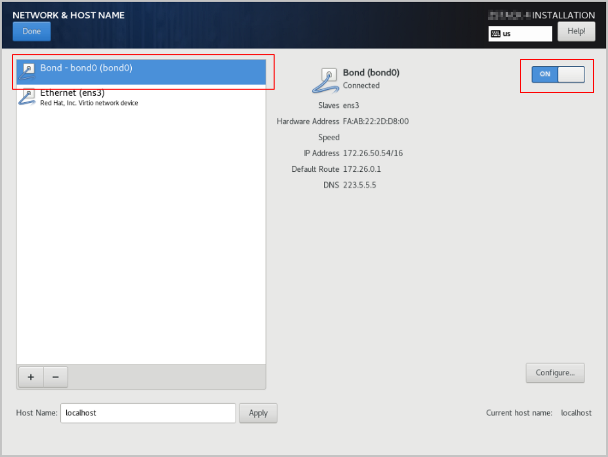
- On the INSTALLATION SUMMARY page, click Root Password to set the root password for the operating system.
- On the INSTALLATION SUMMARY page, click Begin Installation to begin installing the operating system.
Single NIC Deployment
The operating system installation process is identical for both x86 and ARM servers. This chapter uses x86 servers to introduce the detailed installation procedure.
Procedure
-
Select the boot option.
Enter the ISO boot interface and choose the default option to start the operating system installation. You can select based on your actual situation, but we recommend using the graphical user interface (GUI) for installation. If the server does not have a VGA port and only supports serial connections, you can use either VNC or text mode installation methods.
- GUI method
- VNC method
- Text mode method
图 1. System Boot
-
Review the installation configuration summary.
This page displays the system installation configuration. You can modify the configuration as needed. By default, ZStack ZSphere is configured with the following settings:
- Keyboard: English (US)
- Language Support: English (United States)
- Time & Date: Asia/Shanghai (UTC+8). We recommend that you check the host's time in advance and configure it to the current time and time zone.
图 2. System Installation Interface
-
Select the installation mode.
图 3. Select Installation Mode
-
Configure the disk partitions.
-
For Storage Configuration, we recommend selecting
Automatic to automatically configure the disk
partitions.
If you need to manually configure disk partitions, refer to the following guidelines based on the BIOS boot mode:
- UEFI Mode:
- /boot: This directory stores the core files needed for Linux boot. We recommend allocating 1 GB of space.
- /boot/efi: This directory stores the UEFI boot files. We recommend allocating 500 MB.
- swap: This is the swap area. We recommend allocating 32 GB.
- /: This is the root directory for the Linux system. We recommend allocating all remaining space.
- Legacy Mode:
- /boot: This directory stores the core files needed for Linux boot. We recommend allocating 1 GB of space.
- swap: This is the swap area. We recommend allocating 32 GB.
- /: This is the root directory for the Linux system. We recommend allocating all remaining space.
Note:
- The above values represent the recommended partition sizes for ZStack ZSphere (total disk capacity should be greater than 300 GB).
- In Legacy mode, if the system disk capacity exceeds 2 TB, you need to configure a BIOS boot partition to support GPT partitioning. UEFI mode does not have this limitation and supports GPT partitioning.
- UEFI Mode:
图 4. Configure Disk Partitions
-
For Storage Configuration, we recommend selecting
Automatic to automatically configure the disk
partitions.
-
Start configuring the NIC.
- On the INSTALLATION SUMMARY page, click Network & Host Name to access the NETWORK & HOST NAME page.
- Select a NIC from the list on the left, such as Ethernet (ens3).
- Click Configure.
图 5. Configure NIC 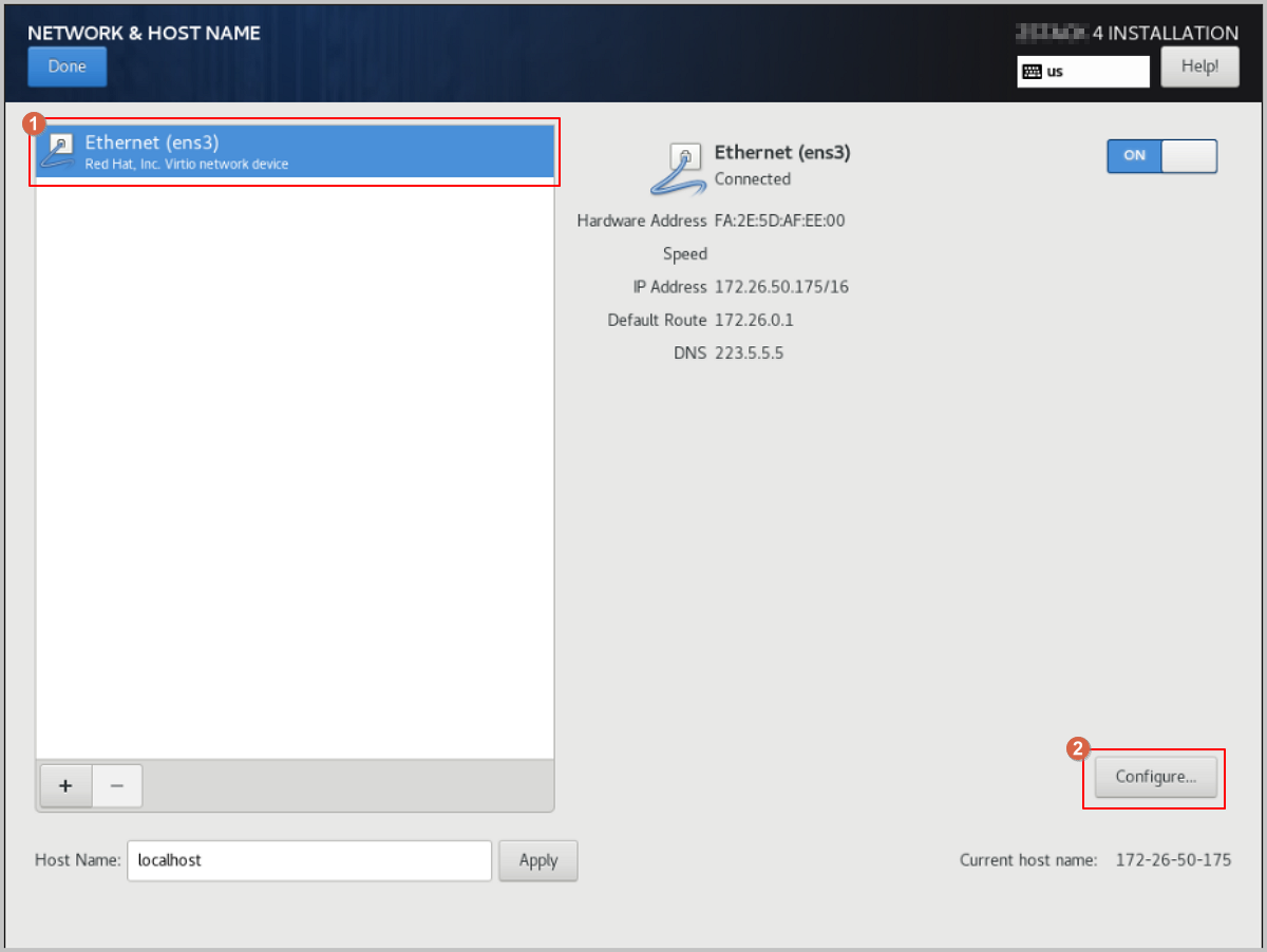
-
Configure a static IP address for the NIC.
- In the Editing ens3 dialog, click IPv4 Settings.
- For Method, choose the IP address acquisition method as needed. For example, select Manual to specify the IP address manually.
- Click Add to add an IP address entry, and configure the IP address, netmask, and gateway as needed.
图 6. Configure Static IP Address 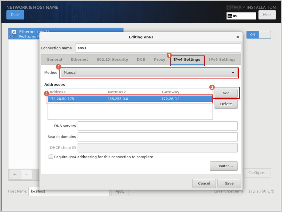
-
Configure the NIC to activate automatically.
- In the Editing ens3 dialog, click General, then select the Connect automatically with priority checkbox to set the NIC for automatic activation.
- Review the configuration and click Save.
图 7. Configure NIC to Activate Automatically 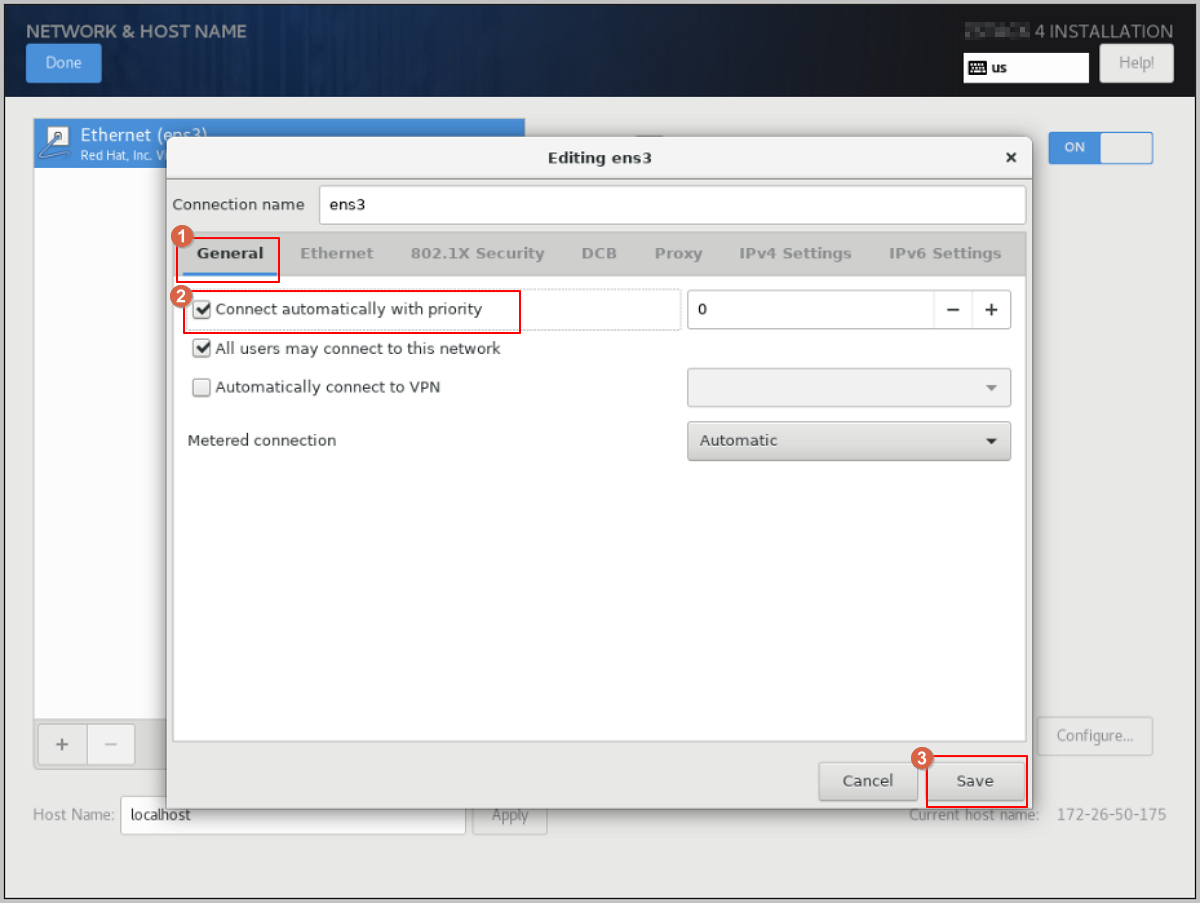
-
Complete the NIC configuration.
- Return to the NETWORK & HOST NAME page, and confirm that you have selected the correct NIC and that the NIC status is ON.
- Click Done to return the INSTALLATION SUMMARY page.
图 8. Check NIC Configuration 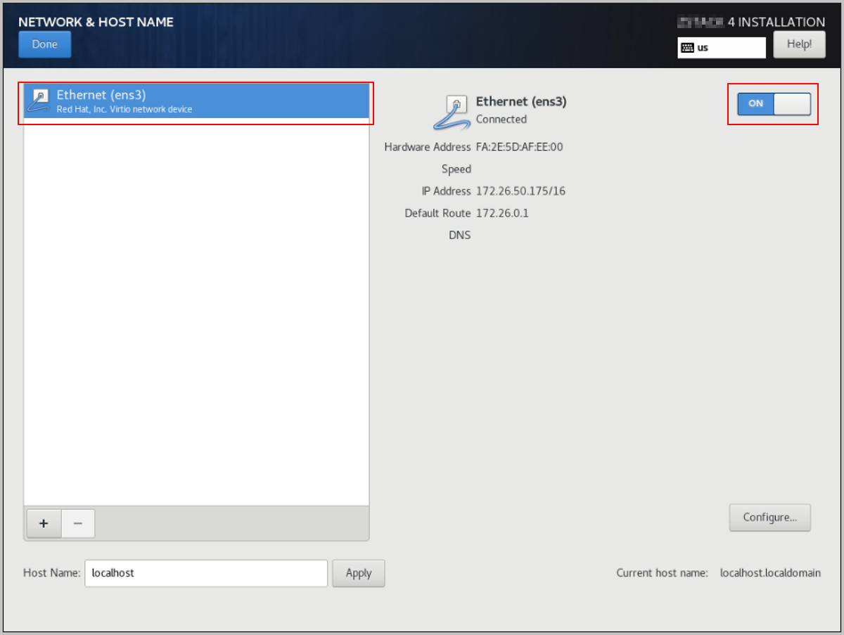
- On the INSTALLATION SUMMARY page, click Root Password to set the root password for the operating system.
- On the INSTALLATION SUMMARY page, click Begin Installation to begin installing the operating system.
Install Through TUI
This chapter describes the complete procedure for deploying a Compute Node from an ISO, configuring the management network as a bond in the TUI, and installing the management node on that compute node.
Procedure
-
Select the boot option.
Enter the ISO boot interface and choose the default option to start the operating system installation. You can select based on your actual situation, but we recommend using the graphical user interface (GUI) for installation. If the server does not have a VGA port and only supports serial connections, you can use either VNC or text mode installation methods.
- GUI method
- VNC method
- Text mode method
图 1. System Boot
-
Enter the INSTALLATION SUMMARY wizard.
After the installation boot screen loads automatically, the INSTALLATION SUMMARY page appears. On this page, focus on the following three configuration items: Installation Destination, Software Selection, and Root Password.
图 2. INSTALLATION SUMMARY Overview 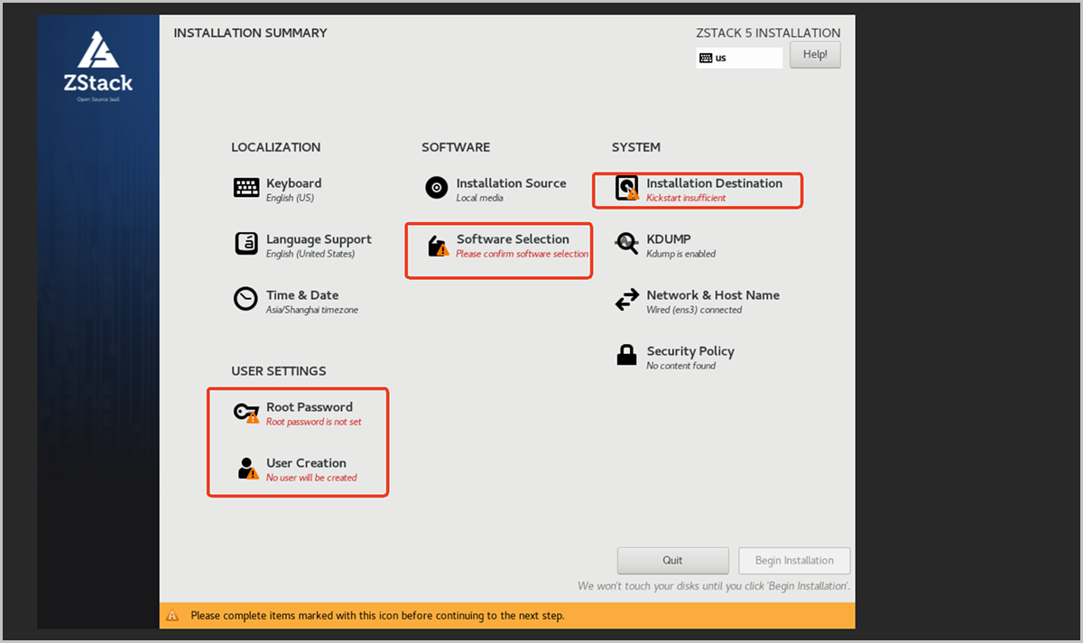
-
Configure Installation Destination.
- Click Installation Destination.
- Under Local Standard Disks, select a disk to use as the system disk.
- Keep Storage Configuration set to the default Automatic.
- Click Done in the upper-left corner to return.
图 3. Select the System Disk 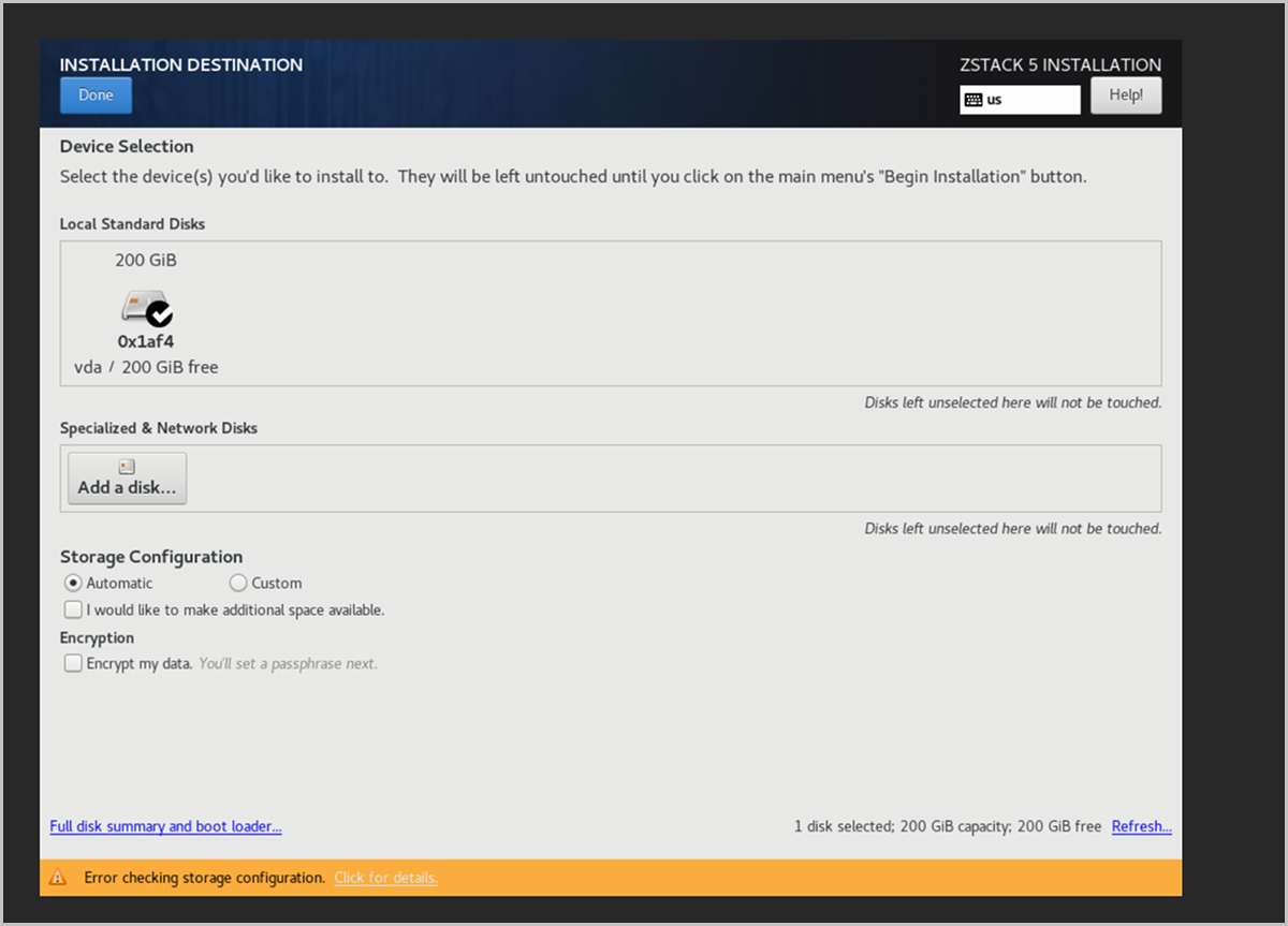
-
Configure Software Selection.
- Click Software Selection.
- Under Base Environment, select ZStack ZSphere Compute Node for the compute node mode.
- Click Done in the upper-left corner to return.
图 4. Select the Compute Node Mode 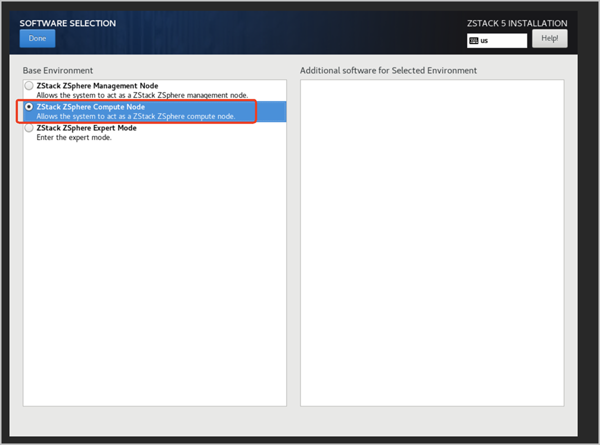
-
Configure the Root Password.
-
Start the installation and wait for it to finish.
Verify that all items marked with red boxes are configured (no yellow warning bars remain), and click Begin Installation in the lower-right corner to start the installation.
图 5. Begin Installation 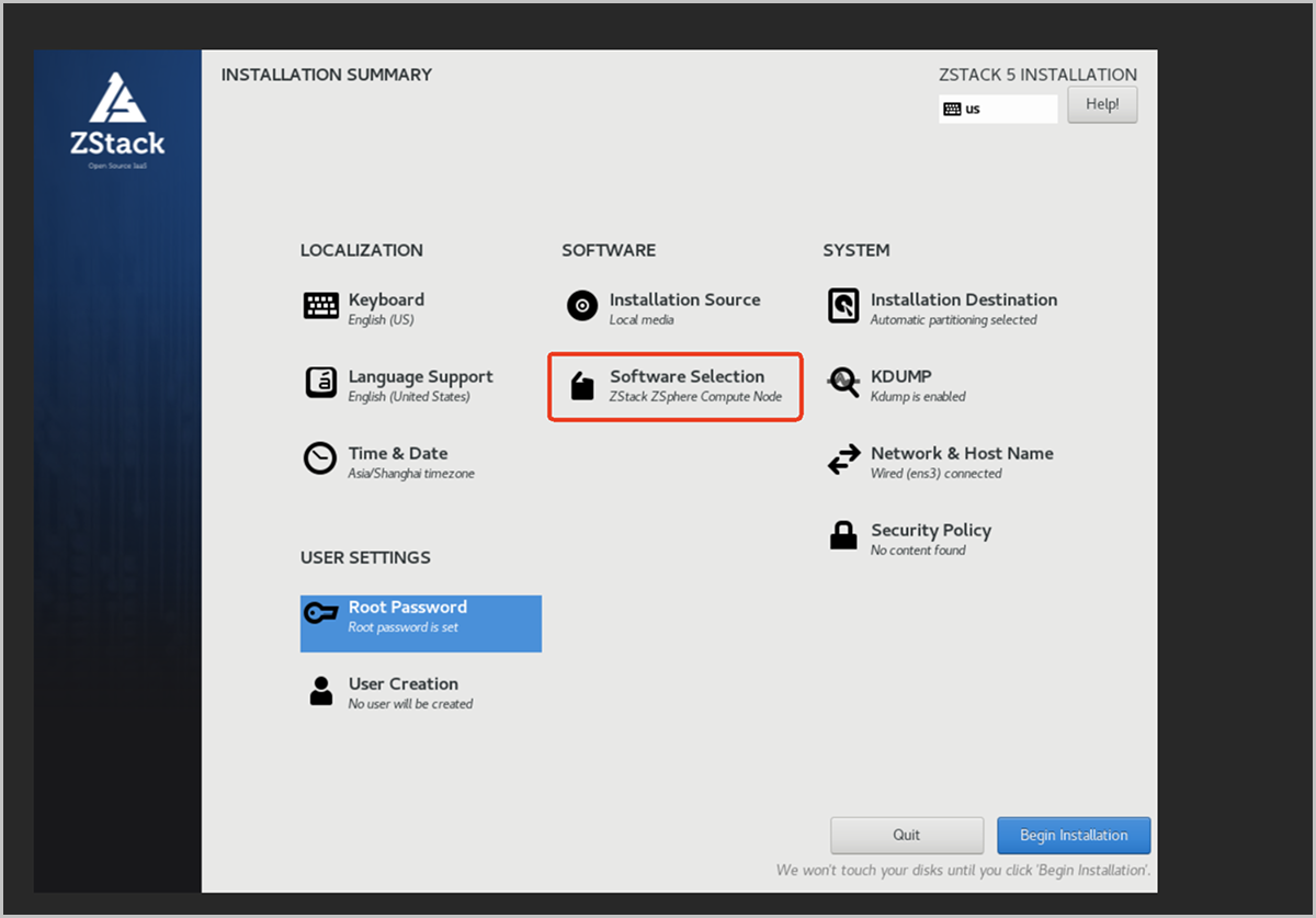
The installation completes automatically and requires no manual intervention. After the installation finishes, the system reboots and the TUI appears.
-
Enter the TUI main screen and complete root authentication.
The TUI is divided into four information areas:
- NODE INFO: Node uptime, load, CPU, and memory usage.
- DISK INFO: Disk mount points and capacity.
- NIC INFO: NIC names and IP addresses. The default NIC, such as ens3, is displayed at first boot.
- VM INFO: List of virtual machines on the current node.
The shortcut keys are shown at the bottom of the screen:- <F2> System Configuration: Enter system configuration.
- <F12> Reboot/Poweroff: Reboot or shut down the system.
图 6. TUI Screen 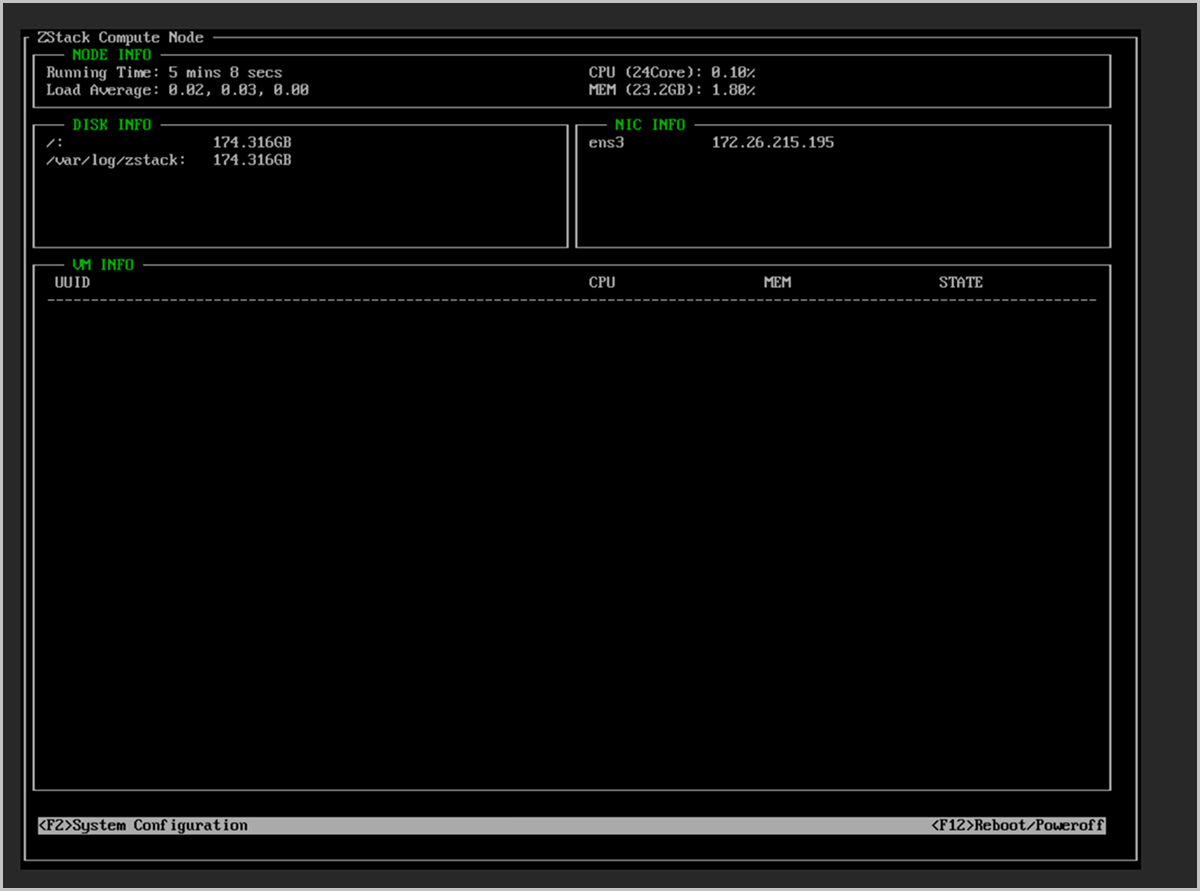
- Press F2 to enter system configuration. The ROOT PASSWORD authentication dialog box appears.
- Enter the root password and press Enter to confirm.
图 7. Enter the Root Password for Authentication 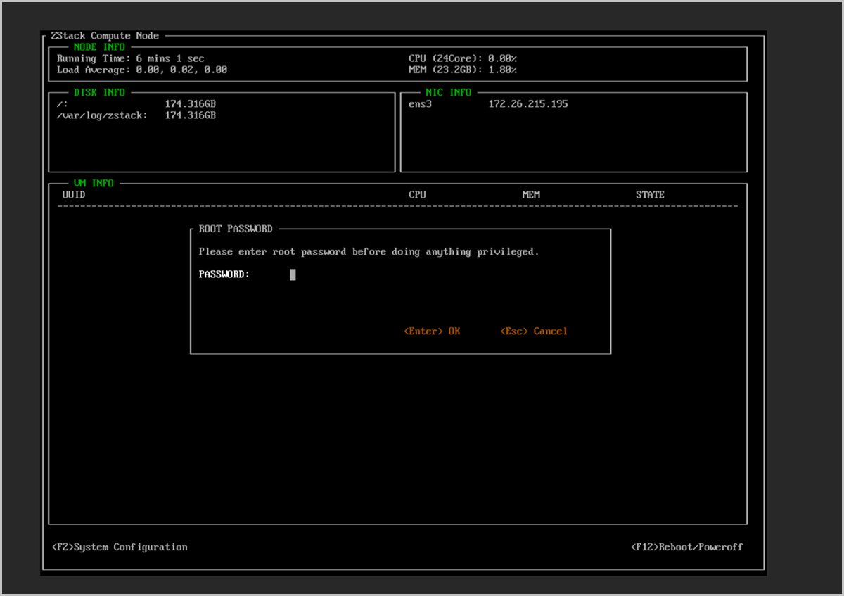
-
Open the Configure Networks settings.
After authentication, the System Configuration menu appears.
-
Press the A key to trigger the Link <A>ggregation operation.
Note: Make sure the keyboard is in uppercase mode. Otherwise, pressing A will not start the bond creation process.
图 8. Select a NIC and Trigger Link Aggregation 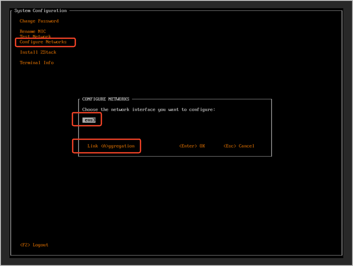
-
Press the A key to trigger the Link <A>ggregation operation.
-
Select the bond mode.
- In the CONFIGURE BOND dialog box that appears, select a bond mode.
- This chapter uses Active-Backup as an example. Press Enter to confirm.
图 9. Select the Active-Backup Bond Mode 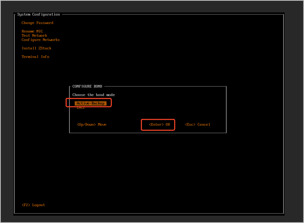
-
Name the bond and select slave NICs.
The CONFIGURE BOND SLAVE dialog box appears. Configure the following settings.
图 10. Enter the Bond Name and Select Slave NICs 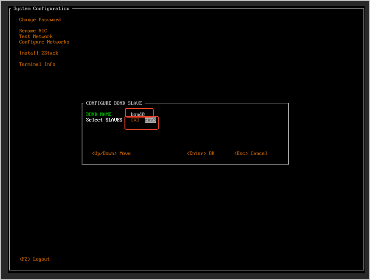
-
Confirm the bond configuration.
The CONFIGURE BOND NETWORK CONFIRM warning dialog box appears with the following message:
Be careful! Changing the network configuration may cause failure! If you know what you are doing, then enter 'Y' to continue!-
Press the Y key to confirm the configuration.
图 11. Confirm the Bond Network Configuration 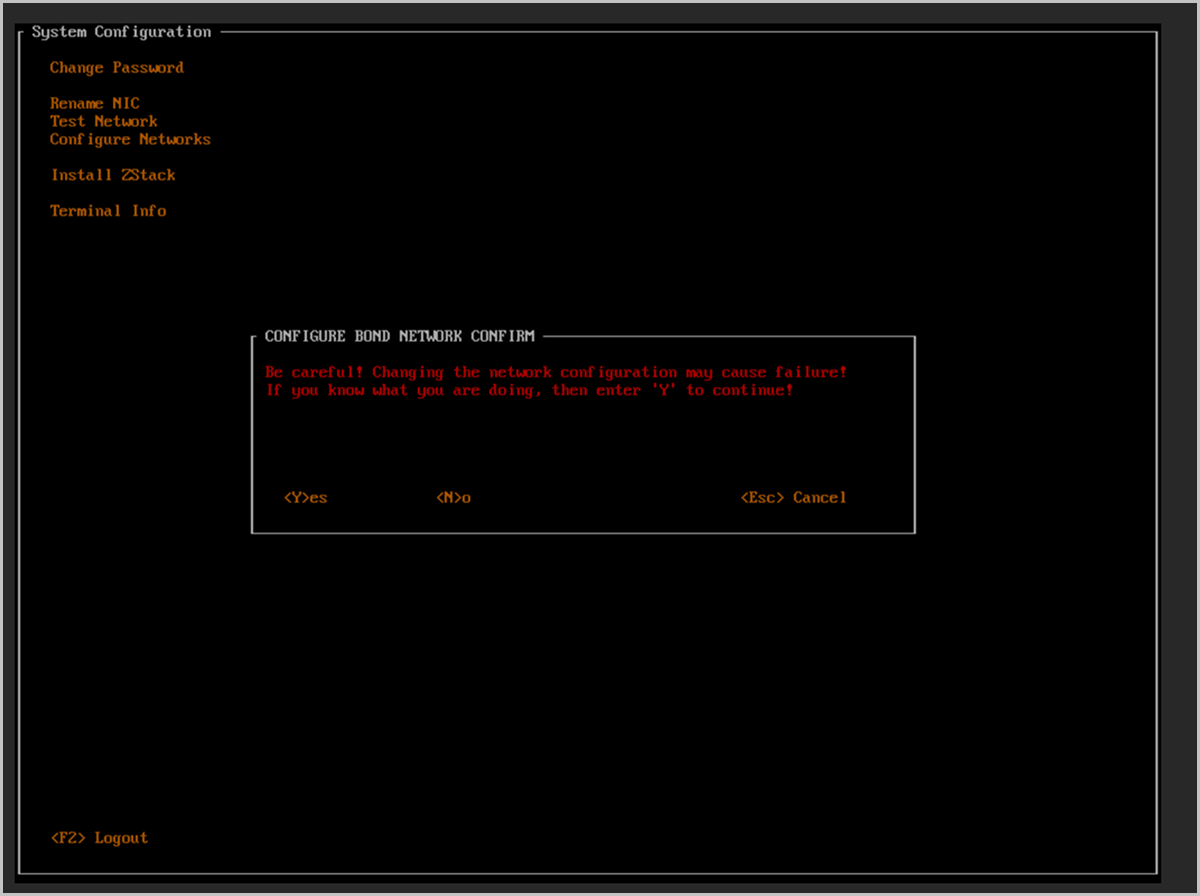
-
When the operation is successful, the SUCCESS dialog box appears with the message
Network configuration is changed successfully!. Press Enter to close it.图 12. Bond Created Successfully 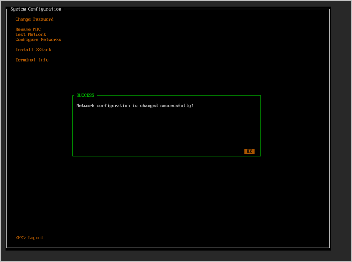
-
Press the Y key to confirm the configuration.
-
Select the bond to configure its IP.
You return to the Configure Networks dialog box.
- In the NIC list, select the bond created in the previous step (for example, bond0).
- Press Enter to enter the IP configuration.
图 13. Select bond0 to Configure the IP Address 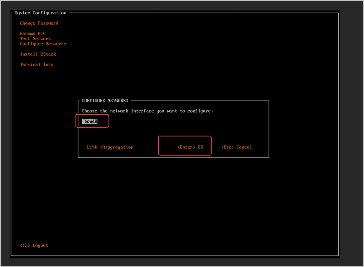
-
Configure the management network IP address.
图 14. IP Configuration Example 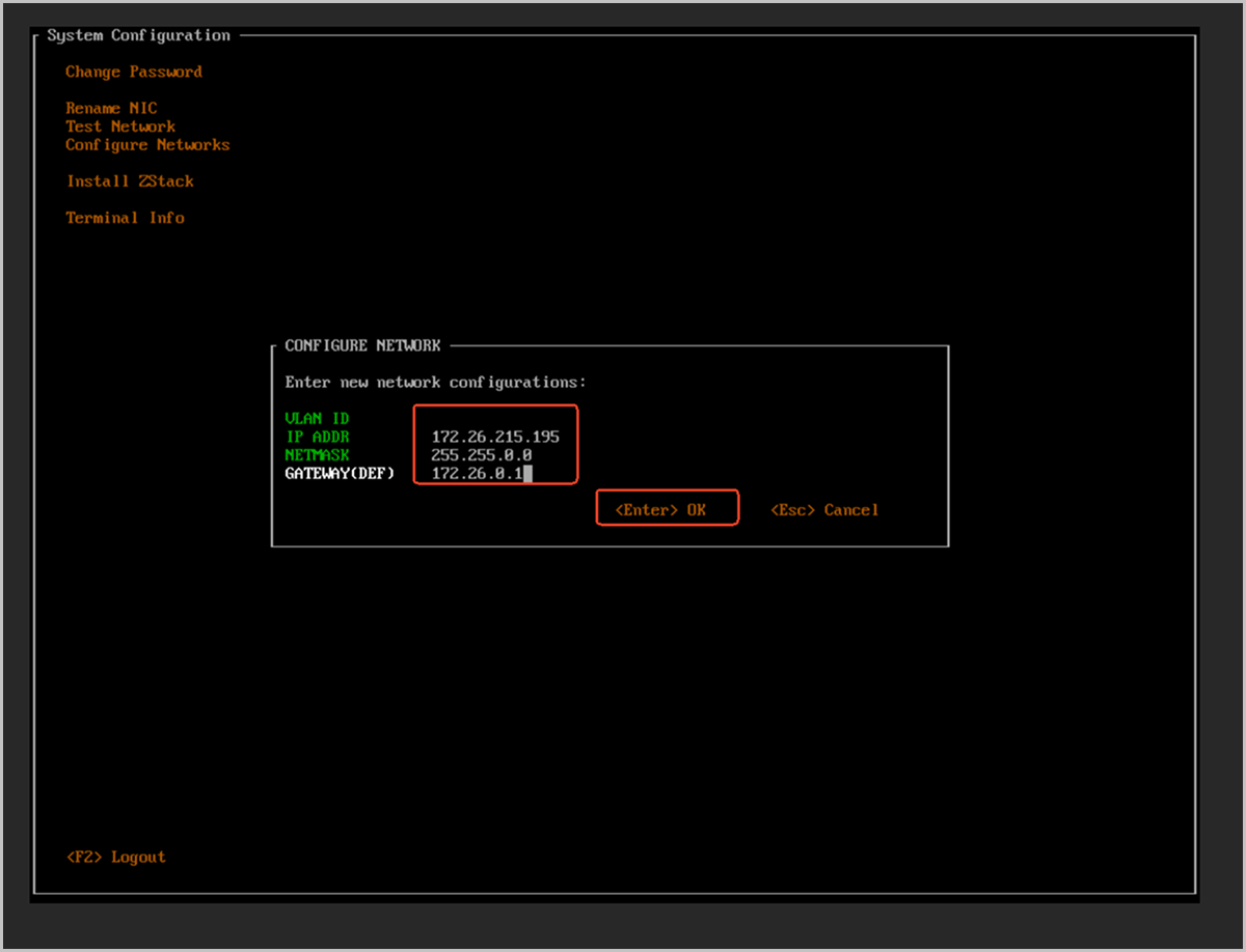
-
Confirm the IP configuration.
-
Press the Y key to confirm.
图 15. Confirm the IP Configuration 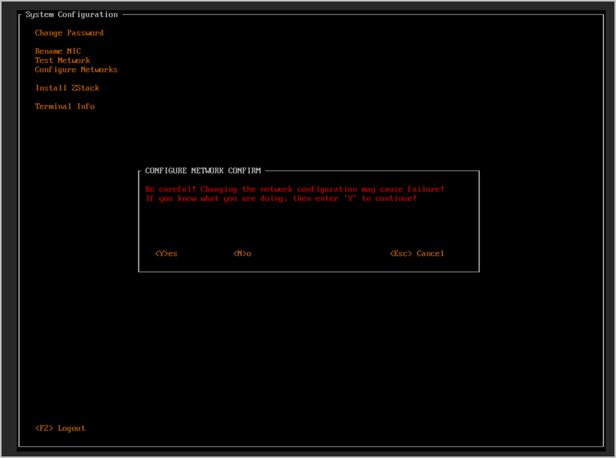
-
The SUCCESS dialog box appears. Press Enter to close it.
图 16. IP Configuration Succeeded 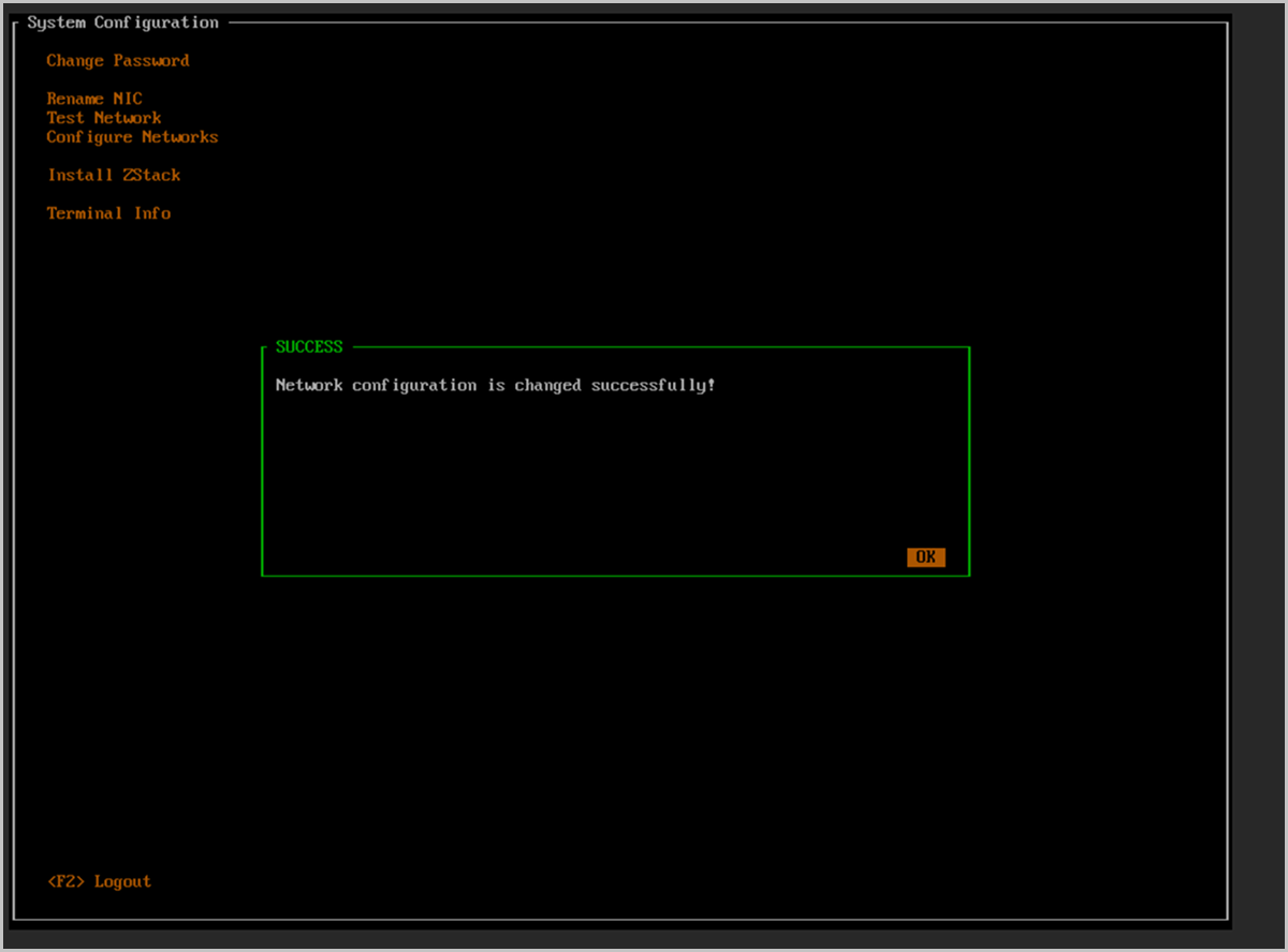
-
Press the Y key to confirm.
-
Open the Install ZStack option.
- Press Esc to return to the System Configuration menu.
- Use the arrow keys to select Install ZStack.
- Press Enter.
图 17. Open the Install ZStack Option 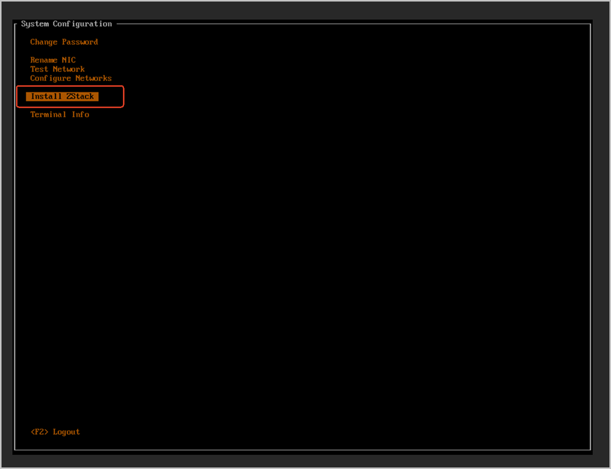
-
Confirm the management node installation.
The INSTALL ZStack warning dialog box appears with the following message:
This process will install a brand new ZStack, please confirm-
Type the full string
install zstack. - Press Enter to confirm.
图 18. Confirm the Management Node Installation 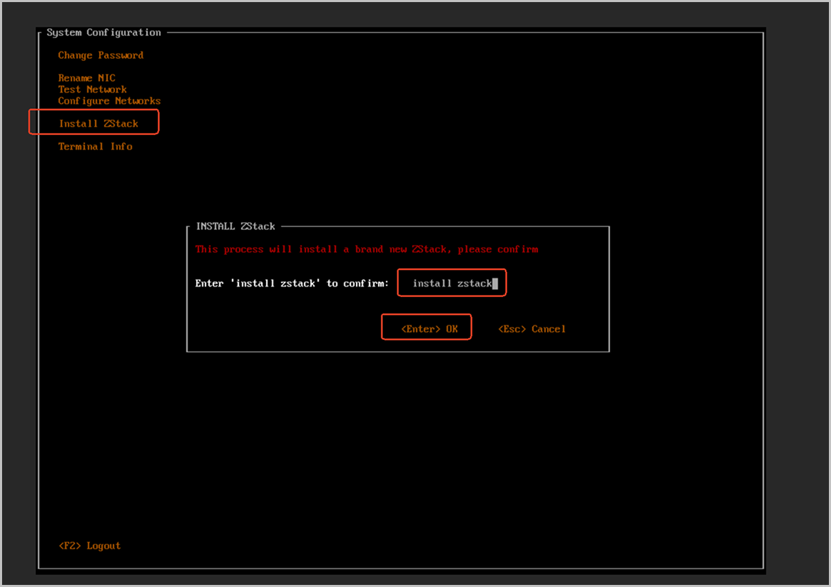
-
Type the full string
-
Wait for the management node installation to complete.
The screen enters a waiting state and displays the message
Please wait.... Wait for the installation to complete.图 19. Management Node Installation in Progress 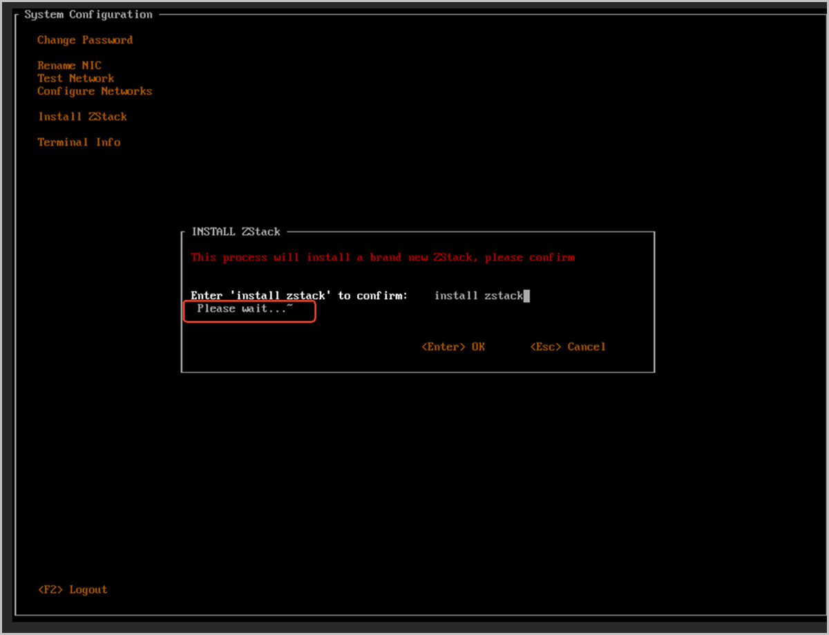
-
After the installation is complete, view the TUI main screen.
After the management node installation completes, the information on the TUI main screen changes as follows:
- DISK INFO: New mount points such as /var/lib/zstack and /usr/local/zstack are added.
- NIC INFO: A new
docker0interface (related to the management service) is displayed, along with the configuredbond0and its IP address (for example, 172.26.215.195).
图 20. TUI Main Screen After Installation 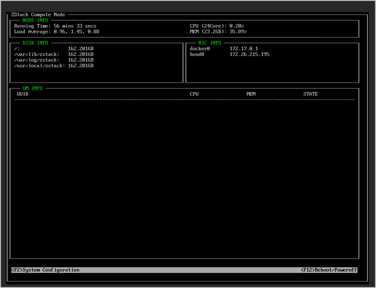
-
Verify the management node status from the command line.
图 21. Verify the Management Node Status from the Command Line 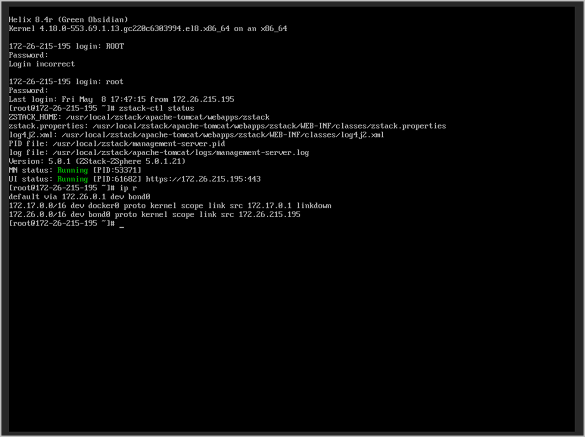
Set Up Management Node HA
Through GUI
Before you begin
- You must install management node services on the selected two servers. For installation instructions, see Install Management Node.
- Ensure both management nodes have gateway addresses on the same network segment and have consistent NIC names.
- Ensure both management nodes are running the same version.
- Ensure the operating system type and architecture are supported and both management nodes run compatible operating system types.
- Ensure both management nodes use the same license type.
Procedure
-
Log in to the UI management interface of either management node.
For a new environment that has not been initialized:
- In the Welcome to Initialization Wizard dialog, click Next. The system automatically detects the management node HA status.
- In the Set Up MN HA dialog, click Go to MN Ops.
- A new browser tab opens displaying the MN Ops page.
图 1. Go to MN Ops from the Initialization Page 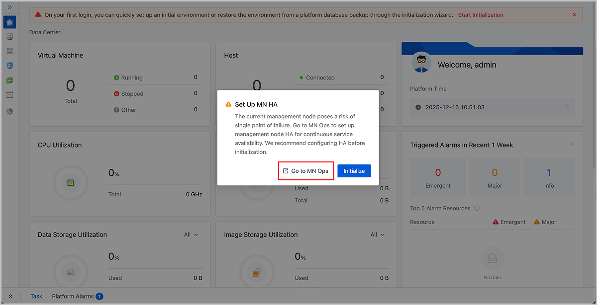
For an existing environment:- In the navigation pane, choose .
- On the MN Monitoring page, click Go to MN Ops.
- A new browser tab opens displaying the MN Ops page.
图 2. Go to MN Ops from the MN Monitoring Page 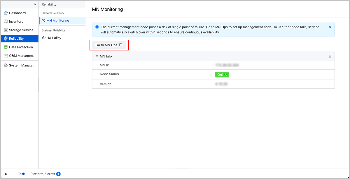
-
On the MN Monitoring page in MN Ops, click Set Up MN HA.
图 3. MN Monitoring 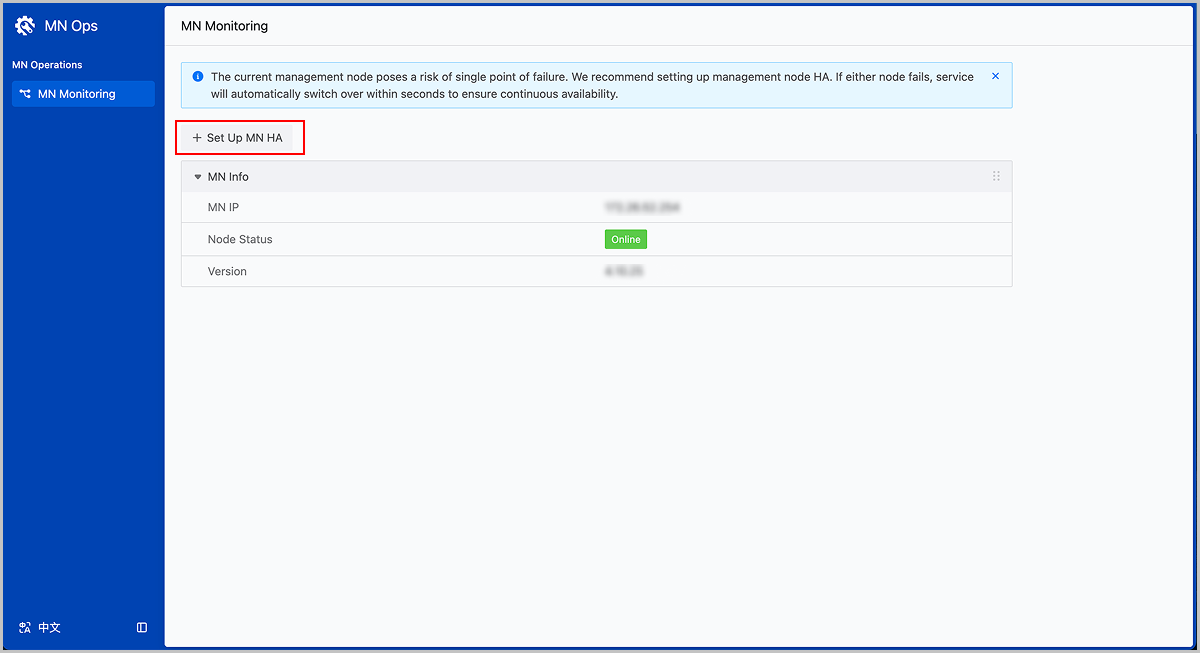
-
In the Set Up MN HA dialog, complete configuring MN, reviewing configuration, and setting up MN HA.
-
For Configure MN, set the following parameters:
- VIP: Configure the VIP for accessing the management interface of the management node environment.Note: Ensure the VIP is in the same network segment as the active management node IP.
- Active MN IP: Display the IP address of the active management node. Specify the SSH username and password for the active management node.
- Standby MN IP: Specify the IP address, SSH username, and SSH password for the standby management node.Note:
- Ensure the standby management node IP is in the same network segment as the active management node IP.
- When setting up management node HA, the management node password can contain English letters, numbers, and these special characters:
-=[];,./~!@#$%^&*()_+|{}:<>?`. If your password does not meet this rule, update it before setting up management node HA.
- Time Sync Server: Uses the active management node IP as the time synchronization server by default.
- Force Sync: Disabled by default. If the databases between active and standby management nodes cannot synchronize automatically, run the zsha2 installation command forcibly on the active management node.
- Database Password: If left blank, the initial database password will be used by default. If the password has been changed, enter the new password here.
图 4. Configure MN 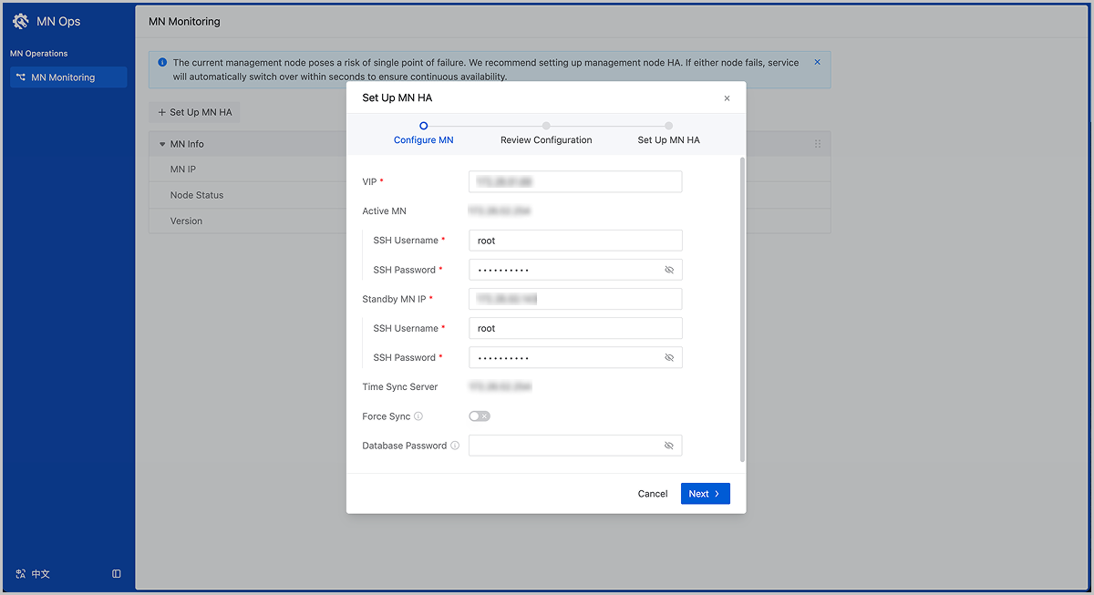
- VIP: Configure the VIP for accessing the management interface of the management node environment.
-
In the Review Configuration step, check the resource information of both active and standby management nodes.
Note:
- Upon confirmation, the system will automatically back up databases from active and standby management nodes before proceeding.
- During this process, the active and standby MNs will shut down and the standby MN's database will be overwritten by the active MN's database. Proceed with caution.
- If you find that the standby management node contains more resources during the resource comparison, and you want to preserve these resources, we recommend that you select the Switch Active/Standby MNs checkbox. When selected, this option switches the roles of active and standby management nodes, using the resource-rich standby management node as the active management node to set up management node HA.
图 5. Review Configuration 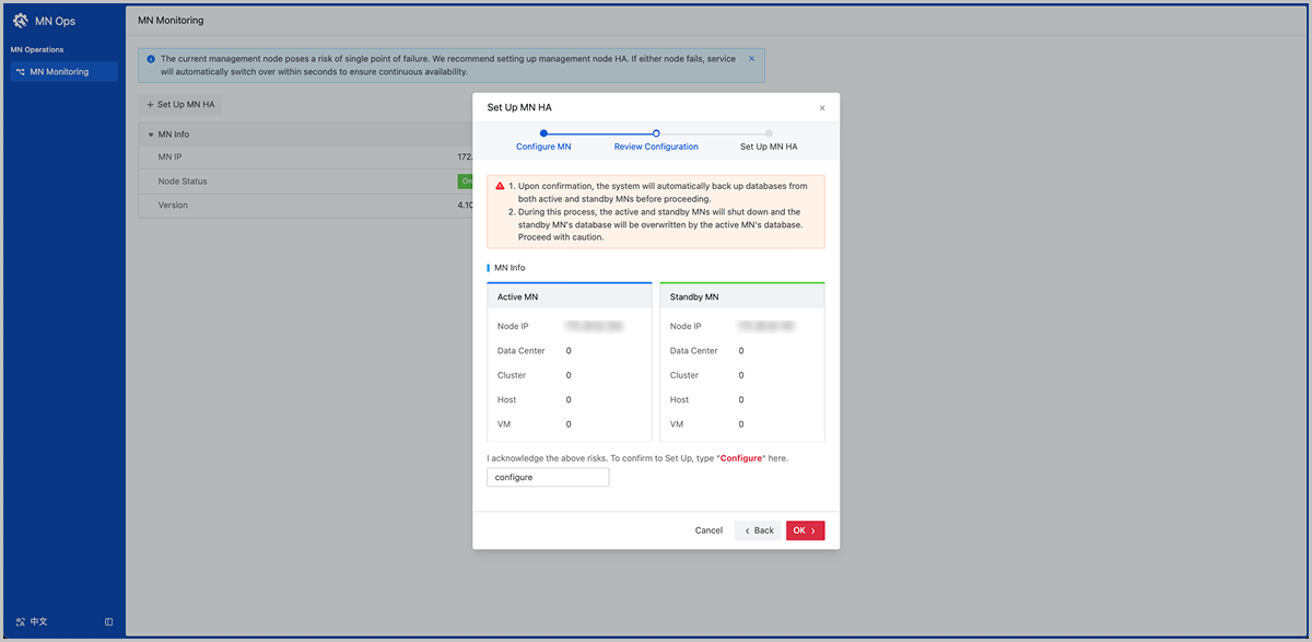
-
In the Set Up MN HA step, view the addition progress and task results.
图 6. Set Up MN HA 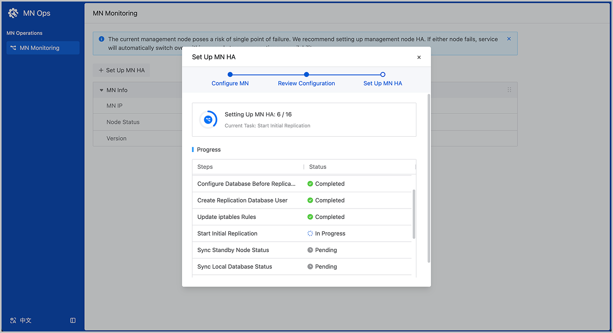
-
For Configure MN, set the following parameters:
-
After the addition completes successfully, click Go to VIP to access the platform management interface through the VIP.
图 7. Go to VIP 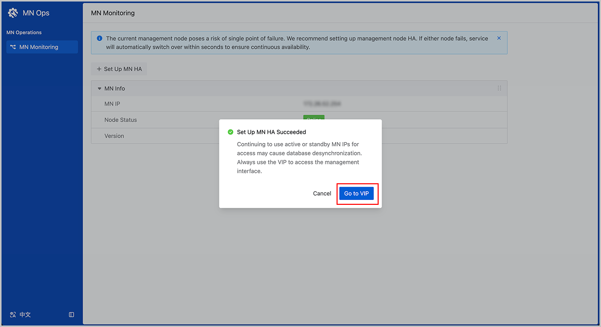
Through CLI
Step 1: Install Operating System
In this scenario, you need to install the management node mode on both selected servers.
Procedure
-
Select the boot option.
Enter the ISO boot interface and choose the default option to start the operating system installation. You can select based on your actual situation, but we recommend using the graphical user interface (GUI) for installation. If the server does not have a VGA port and only supports serial connections, you can use either VNC or text mode installation methods.
- GUI method
- VNC method
- Text mode method
图 1. System Boot
-
Select the installation mode.
图 2. Select Installation Mode
-
Configure the disk partitions.
-
For Storage Configuration, we recommend selecting
Automatic to automatically configure the disk
partitions.
If you need to manually configure disk partitions, refer to the following guidelines based on the BIOS boot mode:
- UEFI Mode:
- /boot: This directory stores the core files needed for Linux boot. We recommend allocating 1 GB of space.
- /boot/efi: This directory stores the UEFI boot files. We recommend allocating 500 MB.
- swap: This is the swap area. We recommend allocating 32 GB.
- /: This is the root directory for the Linux system. We recommend allocating all remaining space.
- Legacy Mode:
- /boot: This directory stores the core files needed for Linux boot. We recommend allocating 1 GB of space.
- swap: This is the swap area. We recommend allocating 32 GB.
- /: This is the root directory for the Linux system. We recommend allocating all remaining space.
Note:
- The above values represent the recommended partition sizes for ZStack ZSphere (total disk capacity should be greater than 300 GB).
- In Legacy mode, if the system disk capacity exceeds 2 TB, you need to configure a BIOS boot partition to support GPT partitioning. UEFI mode does not have this limitation and supports GPT partitioning.
- UEFI Mode:
图 3. Configure Disk Partitions
-
For Storage Configuration, we recommend selecting
Automatic to automatically configure the disk
partitions.
- On the INSTALLATION SUMMARY page, click Root Password to set the root password for the operating system.
- On the INSTALLATION SUMMARY page, click Begin Installation to begin installing the operating system.
Step 2: Configure Management Network
About this task
The following tables list the network information for the management nodes and the VIP settings for Keepalived communication in this scenario.| Server | NIC 1 | NIC 2 | Bond | Bridge | IP Address | Netmask | Gateway |
|---|---|---|---|---|---|---|---|
| MN 1 | eth0 | eth1 | bond0 | br_bond0 | 192.168.195.200 | 255.255.0.0 | 192.168.0.1 |
| MN 2 | eth0 | eth1 | bond0 | br_bond0 | 192.168.196.125 | 255.255.0.0 | 192.168.0.1 |
| - | IP Address | Netmask |
|---|---|---|
| VIP | 192.168.199.151 | 255.255.0.0 |
Note:
- The VIP is used to log in to the UI of the management node. Avoid using the VIP for SSH logins to the management nodes.
- The above data is for example only. You need to modify it based on your actual deployment environment.
- The gateway must be provided by physical network devices and will also serve as network status arbitration detection.
Procedure
-
Log in to the MN 1 operating system and run the following
commands.
# Create the bonded NIC bond0 [root@localhost ~]# zs-bond-lacp -c bond0 # Add NICs eth0 and eth1 to bond0 [root@localhost ~]# zs-nic-to-bond -a bond0 eth0 [root@localhost ~]# zs-nic-to-bond -a bond0 eth1 # After configuring the link aggregation, you need to set up LACP aggregation on the corresponding switch ports. # Create the bridge br_bond0 and specify network IP, netmask, and gateway [root@localhost ~]# zs-network-setting -b bond0 192.168.195.200 255.255.0.0 192.168.0.1 # Check if the aggregated port bond0 was created successfully [root@localhost ~]# zs-show-network ... ---------------------------------------------------------------------------------- | Bond Name | SLAVE(s) | BONDING_OPTS | ---------------------------------------------------------------------------------- | bond0 | eth0 | miimon=100 mode=4 xmit_hash_policy=layer2+3 | | | eth1 | | --------------------------------------------------------------------------------- -
Log in to the MN 2 operating system and run the similar configuration
commands.
Note:
- After adding eth0 and eth1 to bond0, you need to configure LACP aggregation on the corresponding switch ports. Otherwise, network communication will be disrupted.
- After creating the bridge through bond0, the bridge will be named as br_bond0 to provide management network services.
- You need to configure the bridge's IP address, netmask, and gateway according to your actual network environment.
- Once you complete the management network configuration, use the
pingcommand to test it. If configured correctly, the management network IP addresses of the two management nodes should be able topingeach other. - A 10 Gigabit or higher bandwidth is recommended for the management network. A 1 Gigabit bandwidth is acceptable if the network is deployed independently.
Step 3: Configure Business Network
About this task
The following table lists the configuration for the business network in this scenario.| Server | NIC 1 | NIC 2 | Bond | Bridge | IP Address | Netmask | Gateway |
|---|---|---|---|---|---|---|---|
| MN 1 | em1 | em2 | bond1 | - | - | - | - |
| MN 2 | em1 | em2 | bond1 | - | - | - | - |
Procedure
-
Log in to the MN 1 operating system and run the following
commands.
# Create the bonded NIC bond1 [root@localhost ~]# zs-bond-lacp -c bond1 # Add NICs em1 and em2 to bond1 [root@localhost ~]# zs-nic-to-bond -a bond1 em1 [root@localhost ~]# zs-nic-to-bond -a bond1 em2 # After configuring the link aggregation, you need to set up LACP aggregation on the corresponding switch ports. # You do not need to create a bridge for business network # Check if the aggregated port bond1 was created successfully [root@localhost ~]# zs-show-network ... ---------------------------------------------------------------------------------- | Bond Name | SLAVE(s) | BONDING_OPTS | ---------------------------------------------------------------------------------- | bond1 | em1 | miimon=100 mode=4 xmit_hash_policy=layer2+3 | | | em2 | | --------------------------------------------------------------------------------- -
Log in to the MN 2 operating system and run the similar configuration
commands.
Note: After adding em1 and em2 to bond1, you need to configure LACP aggregation
on the corresponding switch ports. Otherwise, network communication will be
disrupted.
Step 4: Install HA Suite
Note: When installing the HA suite with the same configuration, the CLI method
takes precedence over the configuration file method.Install Through CLI
In this scenario, you have installed both servers as the ZStack ZSphere management nodes. To enable high availability for both nodes, you only need to install the HA suite on one of the nodes. If you install the HA suite on MN 1, MN 1 becomes the active management node and MN 2 becomes the standby management node.
Procedure
-
Import the HA suite.
Log in to the MN 1 operating system. Import the HA suite to MN 1 and unzip the HA suite.
# Use scp to import HA suite to MN 1 [root@localhost ~]# ls ZStack-ZSphere-Multinode-HA-Suite.tar.gz # Unzip the suite to get two executable files: zsha2 and zstack-hamon [root@localhost ~]# tar zxvf ZStack-ZSphere-Multinode-HA-Suite.tar.gz zsha2 //Installation and management program for management node high availability zstack-hamon //Monitoring program for management node high availability -
Initialize HA.
Run the following command to install the HA suite on MN 1:
[root@localhost ~]# chmod +x zsha2 zstack-hamon
[root@localhost ~]# ./zsha2 install-ha -nic br_bond0 -gateway 192.168.0.1 -slave "root:password@192.168.196.125" \
-vip 192.168.199.151 -myip 192.168.195.200 -db-root-pw zstack.mysql.password -time-server 192.168.196.125 -cidr 192.168.0.0/16 -yes
Note:
- After executing the installation command, the system will automatically back up the databases of the active and standby management nodes before proceeding with the installation.
- To install the high availability suite, ensure that zsha2 and zstack-hamon are in the same directory. During the installation, zsha2 will automatically deploy zstack-hamon and the related configuration files.
-
Check the management nodes status.
After initializing the HA suite, run the following command to check the status of the management nodes:
# Check the status of Management Node 1
[root@localhost ~]# zsha2 status
Status report from 192.168.195.200
=================================
Owns virtual address:            yes  // MN 1 has acquired the VIP. Only one management node can acquire the VIP at any given time.
Self 192.168.195.200 reachable:   yes // MN1 is reachable.
Gateway 192.168.0.1 reachable:    yes // Current gateway is reachable.
VIP 192.168.199.151 reachable:    yes // VIP is reachable.
Peer 192.168.196.125 reachable:   yes // MN 2 is reachable.
Keepalived status:               active // Keepalived service is active.
ZStack HA Monitor:               active // HA monitoring service is active.
MySQL status:                    mysqld is alive // Database is functioning normally.
MN status: Running [PID:6500] // Management node is operating normally.
UI status: Running [PID:9785] https://192.168.195.200:443 // UI is functioning normally.

Slave Status:
-------------
             Slave_IO_Running: Yes // Slave IO is running normally.
            Slave_SQL_Running: Yes // Slave SQL is running normally.
                   Last_Error:
        Seconds_Behind_Master: 0
                Last_IO_Error:
               Last_SQL_Error:

Warning: Permanently added '192.168.196.125' (ECDSA) to the list of known hosts.
Status report from 192.168.196.125 // Check the status of Management Node 2
================================
Owns virtual address:            no
Self 192.168.196.125 reachable:    yes
Gateway 192.168.0.1 reachable:    yes
VIP 192.168.199.151 reachable:     yes
Peer 192.168.195.200 reachable:   yes
Keepalived status:               active
ZStack HA Monitor:               active
MySQL status:                    mysqld is alive

Slave Status:
-------------
             Slave_IO_Running: Yes
            Slave_SQL_Running: Yes
                   Last_Error:
        Seconds_Behind_Master: 0
                Last_IO_Error:
               Last_SQL_Error:

Note: visit ZStack UI with https://192.168.199.151:443
Note: During
the installation of the HA suite, SSH password-free login has been
automatically configured for both management nodes.
Install Through Configuration File
In this scenario, you have installed both servers as the ZStack ZSphere management nodes. To enable high availability for both nodes, you only need to install the HA suite on one of the nodes. If you install the HA suite on MN 1, MN 1 becomes the active management node and MN 2 becomes the standby management node.
Procedure
-
Import the HA suite.
Log in to the MN 1 operating system. Import the HA suite to MN 1 and unzip the HA suite.
# Use scp to import HA suite to MN 1 [root@localhost ~]# ls ZStack-ZSphere-Multinode-HA-Suite.tar.gz # Unzip the suite to get two executable files: zsha2 and zstack-hamon [root@localhost ~]# tar zxvf ZStack-ZSphere-Multinode-HA-Suite.tar.gz zsha2 //Installation and management program for management node high availability zstack-hamon //Monitoring program for management node high availability -
Create the configuration fie.
Run the following commands to create the initialization configuration file for the HA suite:
[root@localhost ~]# chmod +x zsha2 zstack-hamon [root@localhost ~]# ./zsha2 sample-config > zs-install.config [root@localhost ~]# cat zs-install.config { "gateway": "192.168.0.1", // Arbiter gateway for active and standby management nodes "virtualIp": "192.168.199.151", // The VIP for Keepalived communication "myIp": "192.168.195.200", // Specify the local IP "peerIp": "192.168.196.125", // Specify the Peer management node IP "peerSshUser": "root", // Specify the SSH username for the Peer management node "peerSshPass": "password", // Specify the SSH password for the Peer management node "peerSshPort": 22, // Specify the SSH port for the Peer management node "dbRootPass": "zstack.mysql.password", // Specify the root password for the database on both management nodes (must be the same) "interface": "br_bond0", //Name of the physical device for configuring the VIP. Typically a management network bridge in production environments "timeServer": "192.168.196.125" //Specify the time synchronization server for unified time synchronization } -
Initialize HA.
Run the following command to install the HA suite:
[root@localhost ~]# ./zsha2 install-ha -config zs-install.configNote:
- After executing the installation command, the system will automatically back up the databases of the active and standby management nodes before proceeding with the installation.
- To install the high availability suite, ensure that zsha2 and zstack-hamon are in the same directory. During the installation, zsha2 will automatically deploy zstack-hamon and the related configuration files.
-
Check the management nodes status.
After initializing the HA suite, run the following command to check the status of the management nodes:
# Check the status of Management Node 1
[root@localhost ~]# zsha2 status
Status report from 192.168.195.200
=================================
Owns virtual address:            yes  // MN 1 has acquired the VIP. Only one management node can acquire the VIP at any given time.
Self 192.168.195.200 reachable:   yes // MN1 is reachable.
Gateway 192.168.0.1 reachable:    yes // Current gateway is reachable.
VIP 192.168.199.151 reachable:    yes // VIP is reachable.
Peer 192.168.196.125 reachable:   yes // MN 2 is reachable.
Keepalived status:               active // Keepalived service is active.
ZStack HA Monitor:               active // HA monitoring service is active.
MySQL status:                    mysqld is alive // Database is functioning normally.
MN status: Running [PID:6500] // Management node is operating normally.
UI status: Running [PID:9785] https://192.168.195.200:443 // UI is functioning normally.

Slave Status:
-------------
             Slave_IO_Running: Yes // Slave IO is running normally.
            Slave_SQL_Running: Yes // Slave SQL is running normally.
                   Last_Error:
        Seconds_Behind_Master: 0
                Last_IO_Error:
               Last_SQL_Error:

Warning: Permanently added '192.168.196.125' (ECDSA) to the list of known hosts.
Status report from 192.168.196.125 // Check the status of Management Node 2
================================
Owns virtual address:            no
Self 192.168.196.125 reachable:    yes
Gateway 192.168.0.1 reachable:    yes
VIP 192.168.199.151 reachable:     yes
Peer 192.168.195.200 reachable:   yes
Keepalived status:               active
ZStack HA Monitor:               active
MySQL status:                    mysqld is alive

Slave Status:
-------------
             Slave_IO_Running: Yes
            Slave_SQL_Running: Yes
                   Last_Error:
        Seconds_Behind_Master: 0
                Last_IO_Error:
               Last_SQL_Error:

Note: visit ZStack UI with https://192.168.199.151:443
Note: During
the installation of the HA suite, SSH password-free login has been
automatically configured for both management nodes.
Manage ZStack ZSphere Service
Check MN Service Status
zstack-ctl status command to
check the running status of the services related to the ZStack ZSphere management
node.[root@localhost ~]# zstack-ctl status
ZSTACK_HOME: /usr/local/zstack/apache-tomcat/webapps/zstack
zstack.properties: /usr/local/zstack/apache-tomcat/webapps/zstack/WEB-INF/classes/zstack.properties
log4j2.xml: /usr/local/zstack/apache-tomcat/webapps/zstack/WEB-INF/classes/log4j2.xml
PID file: /usr/local/zstack/management-server.pid
log file: /usr/local/zstack/apache-tomcat/logs/management-server.log
version: 5.0.3 (ZStack-enterprise 5.0.3)
MN status: Running [PID:123135]
UI status: Running [PID:795] https://10.0.0.254:443zstack-ctl ui_status
command to check the status of the Web UI
separately.[root@localhost ~]# zstack-ctl ui_status
UI status: Running [PID:8459] https://10.0.0.254:443Change MN Service Status
zstack-ctl restart_nodezstack-ctl stop && zstack-ctl start# This command will start both the management node and Web UI services
[root@localhost ~]#zstack-ctl startCheck Service Status of MN HA
You can run the zsha2 status command to check if the zsha2 service is running normally.
Export Log of MN HA
[root@localhost ~]# zsha2 collect-log
Collecting logs ...
Collected log: zsha2-log-2018-09-17T154358+0800.tgz

# Unpack the log archive
[root@localhost ~]# tar zxvf zsha2-log-2021-01-17T154358+0800.tgz
tmp/zsha2-log588815976/
tmp/zsha2-log588815976/zsha2-status.log
tmp/zsha2-log588815976/zstack-ha.log
tmp/zsha2-log588815976/keepalived.data
tmp/zsha2-log588815976/zs-vip-192.168.199.151.log
tmp/zsha2-log588815976/keepalived_status.log