Resource Virtualization
Compute Virtualization
Overview
Compute virtualization abstracts physical server resources into logical resources through virtualization technology, enabling a single physical server to function as multiple isolated virtual machines. It pools hardware resources such as CPU, memory, disk, and I/O devices into a virtual resource pool for unified dynamic management. Consequently, it improves resource utilization, reduces system management costs, and increases IT agility to adapt to business changes.
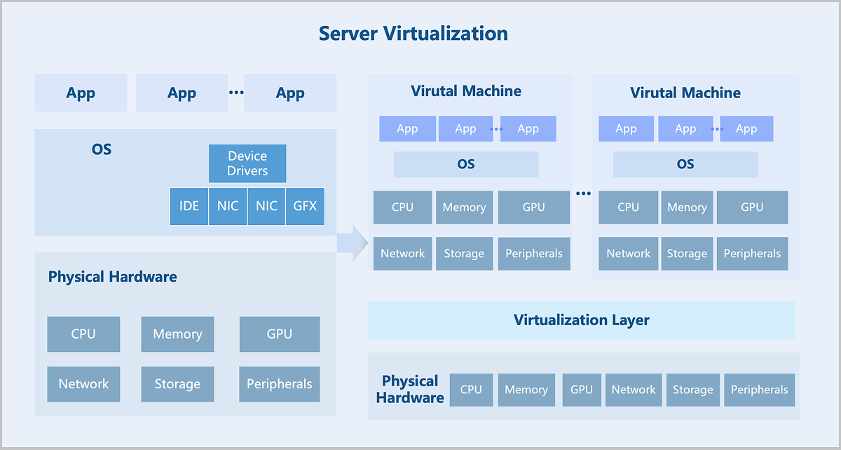
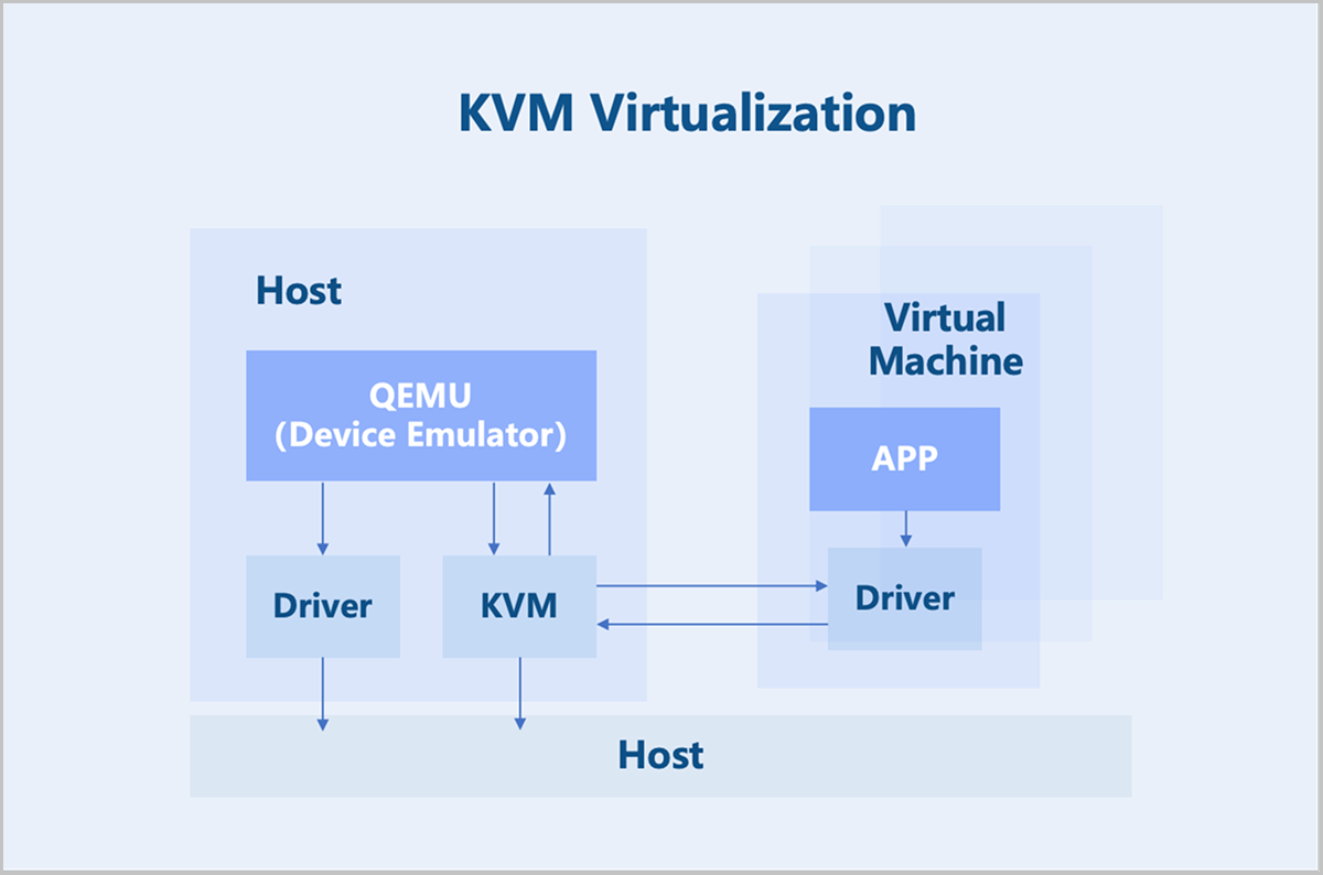
ZStack ZSphere adopts a KVM-based hardware virtualization technology. As a Linux kernel module, KVM turns the Linux kernel into a hypervisor. KVM operates as a process within the Linux system and is scheduled by the standard Linux scheduler. As a result, KVM can leverage existing Linux kernel functionalities, such as memory management and CPU scheduling. However, KVM itself only provides CPU and memory virtualization. I/O device virtualization requires QEMU for full functionality. QEMU is a user-mode device emulator that provides virtual device models for virtual machines. It is responsible for creating, calling, and managing various virtual devices.
Key Features
CPU Virtualization
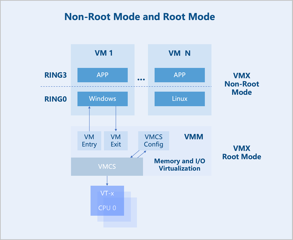
In the x86 architecture, CPUs generally have four privilege levels (RING0 to RING3) for operating systems and applications to access hardware. Linux uses only two of these levels: RING0 (kernel mode) and RING3 (user mode).
VMX Root Mode and VMX Non-Root Mode: For hardware-assisted virtualization, CPUs introduce two operation modes to enable virtual machines to run without modifying the operating system: VMX root mode and VMX non-root mode. The host runs in root mode, with its kernel in RING0 and user-mode programs in RING3. The virtual machine runs in non-root mode, with its kernel in RING0 and user-mode programs in RING3.
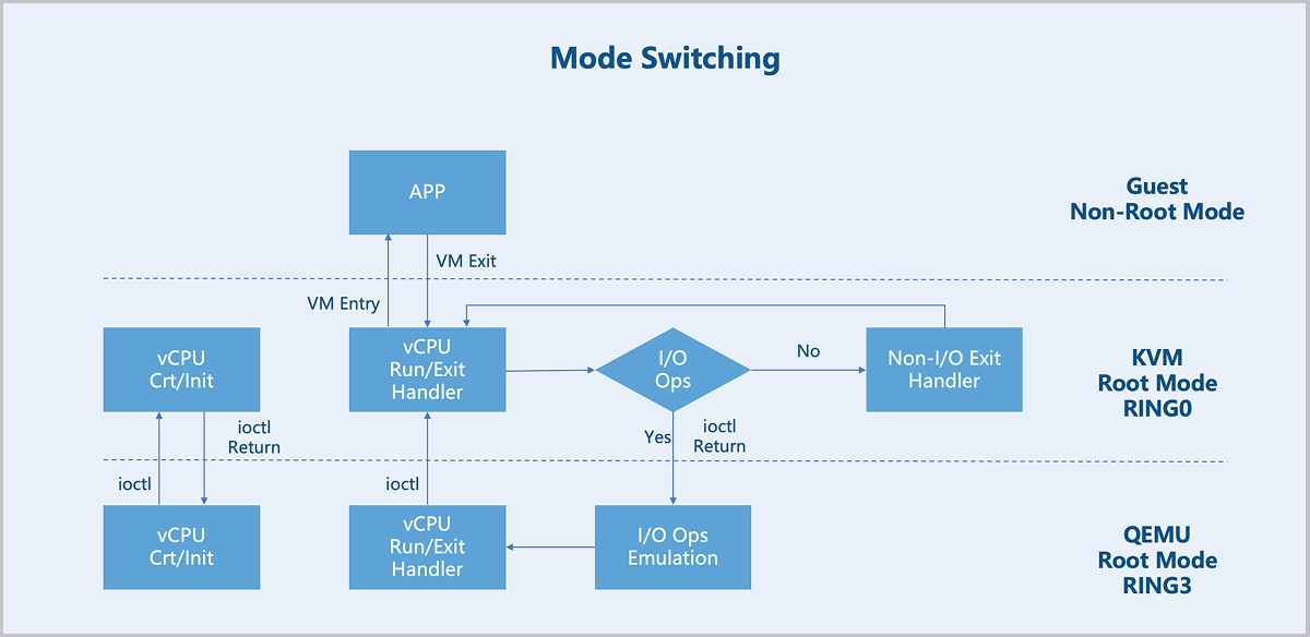
VM Exit and VM Entry: A switch from non-root mode to root mode occurs when a virtual machine in non-root mode encounters external interrupts, page faults, or actively executes the VMCALL instruction to invoke VMM services. This entire process is called VM Exit. Conversely, when the VMM explicitly executes either VMLAUNCH or VMRESUME instruction to switch to non-root Mode, the hardware automatically loads the virtual machine context and executes VM instructions. This transition is called VM Entry.
After a virtual machine triggers a VM Exit from non-root mode to root mode, KVM takes further action based on the exit reason. If the exit is due to an I/O operation, KVM delegates the processing to QEMU. For non-I/O exits, KVM handles them directly. After processing, KVM initiates a VM Entry to switch back to non-root mode for virtual machine execution.
Memory Virtualization
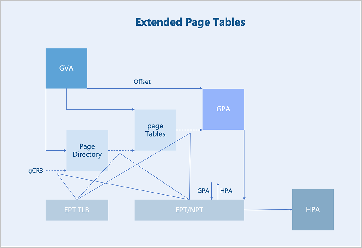
The Virtual Machine Monitor (VMM) manages and allocates physical memory for each virtual machine. The guest OS sees a virtualized Guest Physical Address (GPA) space. The OS memory management module maps Guest Virtual Addresses (GVAs) to GPAs. The target address in instructions is also a GPA. In a non-virtualized environment, such an address would be the actual physical address. However, in a virtualized scenario, this address cannot be used directly. Instead, the VMM must first translate the GPA into a Host Physical Address (HPA), which is then executed by the physical processor.
- Maintaining the mapping relationship between GPAs and HPAs.
- Translating GPAs into HPAs whenever a virtual machine accesses a GPA based on the established mapping.
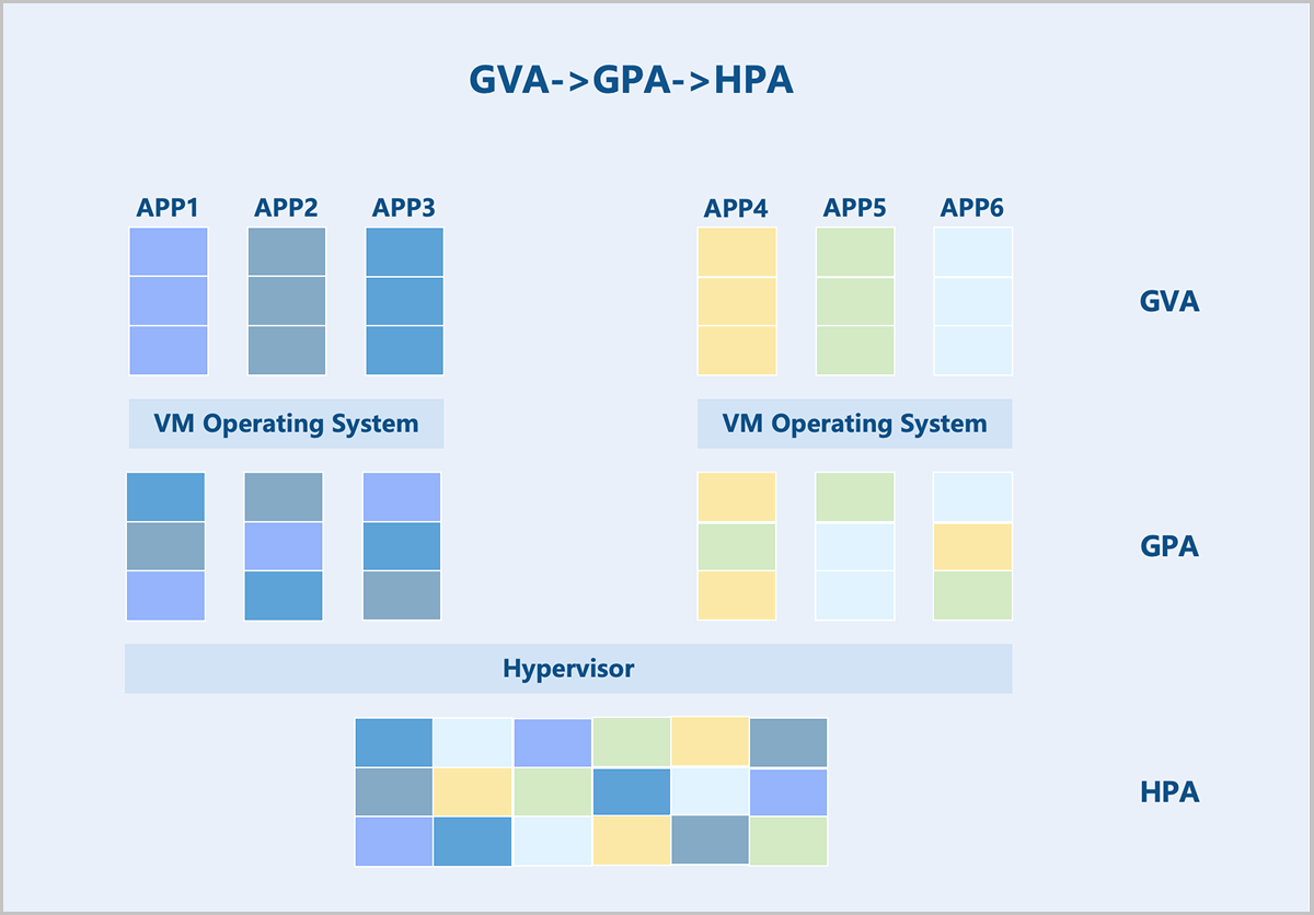
Hardware-assisted memory virtualization uses Extended Page Tables (EPT) technology to translate GVAs into HPAs at the hardware level.
Device Virtualization
There are three main approaches to device virtualization: device emulation, paravirtualized devices, and device passthrough.
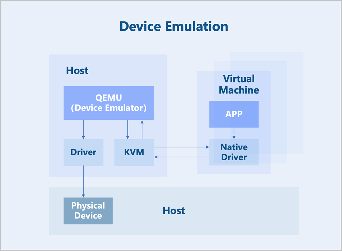
Device Emulation
Device emulation uses the device models provided by QEMU to fully emulate interfaces identical to those of physical devices. Consequently, the VM operating system can use these devices with its native drivers. However, device emulation can only replicate devices with basic functionalities and does not support complex features or models. While fully emulated devices offer good compatibility, they suffer from lower performance since they are purely software-based emulation.
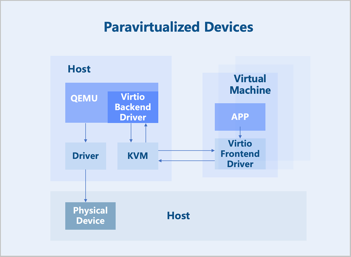
Paravirtualized Devices
Paravirtualized devices implement frontend and backend drivers. Utilizing a frontend driver in the virtual machine, requests are directly sent to a backend driver on the host through a transaction-based communication mechanism, significantly reducing context switching overhead and improving performance over full device emulation. However, since the Virtio backend driver is still implemented in QEMU, the I/O processing path involves multiple switches between user space and kernel space. To further enhance performance, the functionality of the Virtio backend driver can be moved into the kernel space. This implementation is known as the Vhost-kernel backend. With this change, data transmission requires only a single switch from user space to kernel space, thereby improving performance.
As technology evolves, moving data processing to user space achieves a greater flexibility. Consequently, modifications to the original Vhost architecture led to the Vhost-user backend, which works with relevant user-space libraries from DPDK and SPDK to further boost performance.
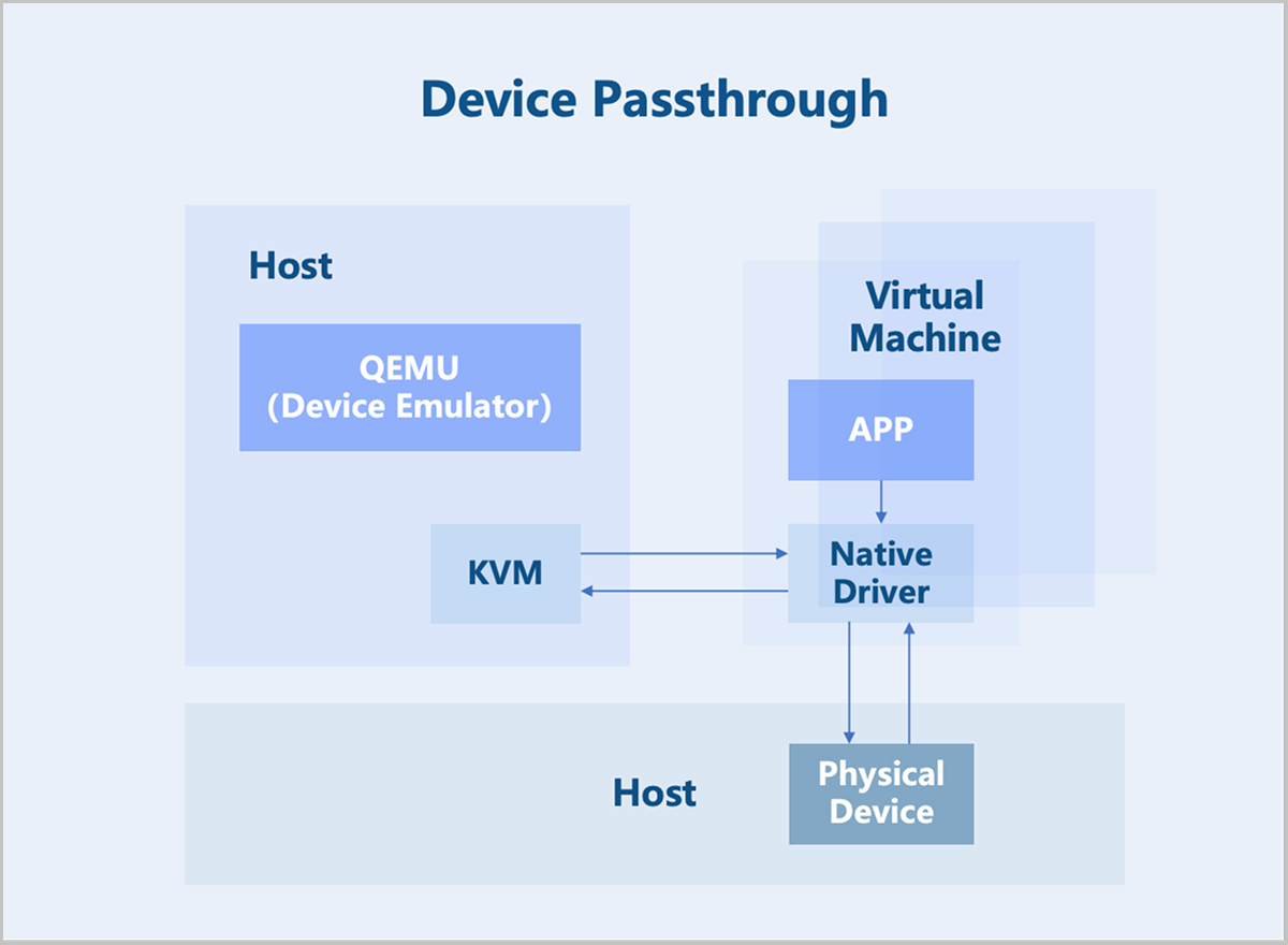
Device Passthrough
Device passthrough uses the hardware-assisted device virtualization technology to directly map a physical PCI/PCIe device to a virtual machine's address space. The virtual machine can use the native device driver to directly operate the devices, achieving performance nearly identical to that of physical devices. Once a physical device is passed through, it is dedicated to that virtual machine and cannot be shared with other VMs.
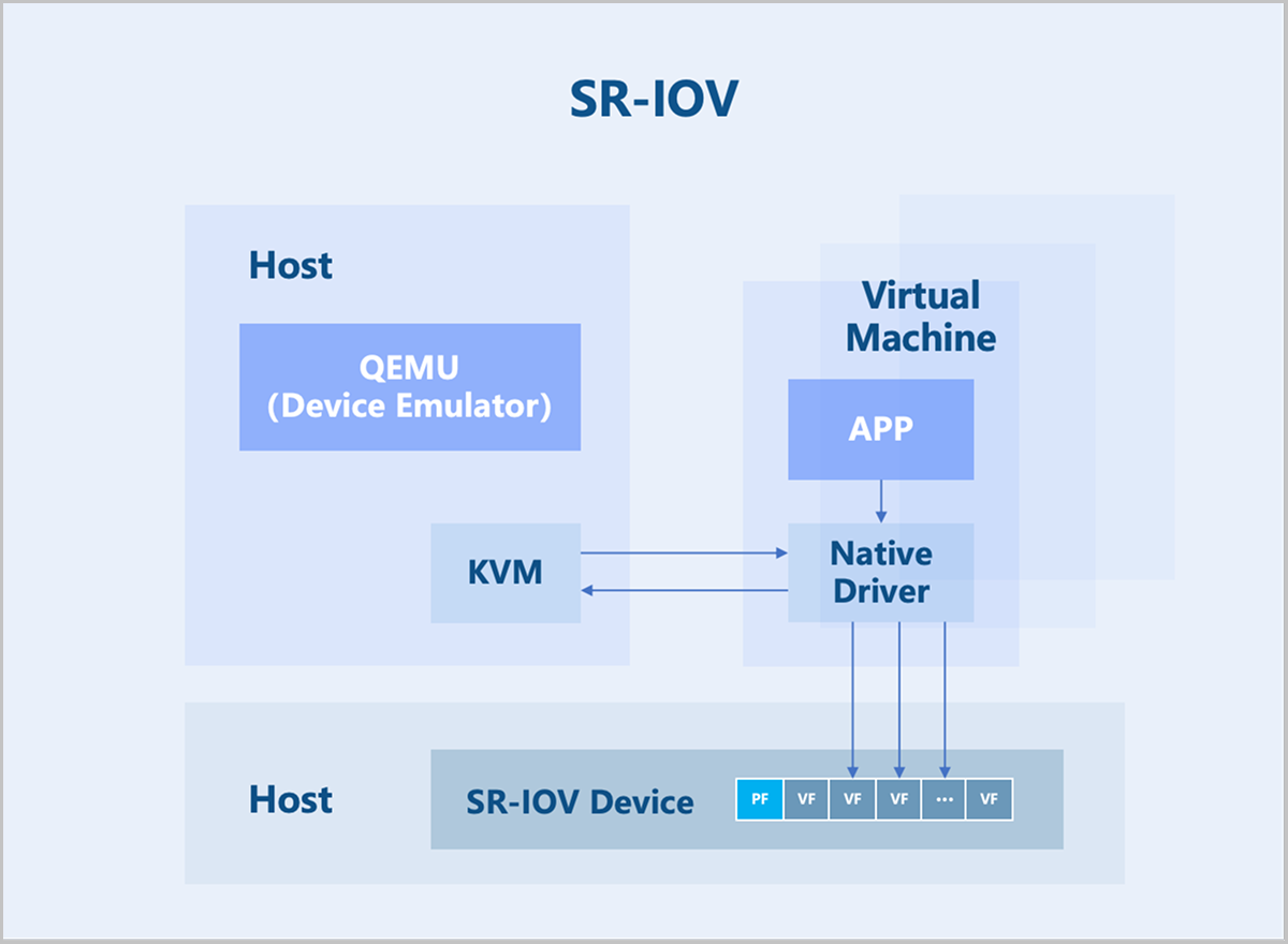
SR-IOV is an extension to the PCIe specification defined by the PCI-SIG. Its purpose is to provide a standardized specification for granting virtual machines independent memory spaces, interrupts, and DMA data streams. SR-IOV enables a single physical PCIe device (Physical Function, PF) to be virtualized into multiple virtual PCIe device devices (Virtual Function, VF). These VFs can then be passed through directly to virtual machines using device passthrough technology. This allows a single physical PCIe device to support multiple virtual machines.
Storage Virtualization
Overview
Storage virtualization pools server storage resources to achieve unified integration, management, and scheduling. It provides various storage interfaces to upper-layer services, allowing business virtual machines to flexibly allocate and use storage space from the resource pool based on their needs. ZStack ZSphere supports integration with both centralized storage and distributed storage.
Key Features
Centralized Storage
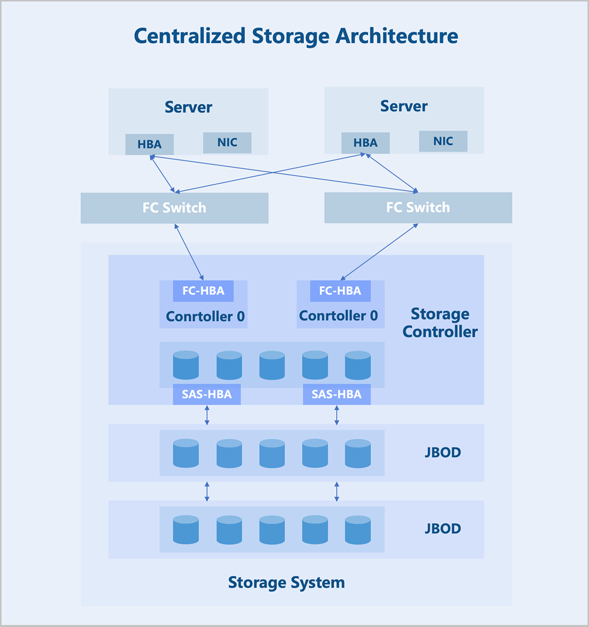
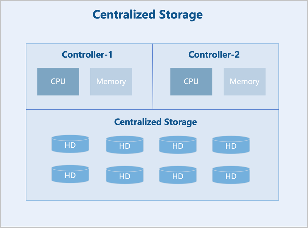
Centralized storage refers to storing data on a central node composed of one or more servers. All services are centrally deployed on this node, which uniformly manages data for subsidiary nodes. Data access is achieved through a single controller. Centralized storage falls into three categories: DAS, NAS, and SAN. You can select the appropriate type based on your data storage needs.
- High Performance and High Reliability: Centralized Storage stores data on a central node composed of one or more servers. It effectively mitigates the risks associated with data fragmentation and enhances both the performance and reliability of the storage system.
- Scalability: Centralized Storage can expand over the network to store more data, allowing the storage system to grow with your business needs.
- Security: Centralized Storage safeguards data security and integrity through security measures such as access control and data encryption.
On architecture: The storage controller is the core component of a centralized storage architecture. Typically, it contains two controllers operating in an active-standby mode to prevent the system-wide failures due to hardware issues. The storage controller features frontend and backend ports. Frontend ports provide storage services to servers, while backend ports expand the storage system capacity. Through backend ports, the storage controller connects to more additional storage devices, forming a large storage pool.
SAN
ZStack ZSphere supports integration with various types of centralized storage. This section focuses on SAN storage, which allows LUN devices allocated by users on the SAN to be directly utilized as storage pools and provisioned to business virtual machines. Unlike file system-based data storage, SAN storage offers advantages such as streamlined deployment, flexible scalability, and high performance. According to actual test results, SAN storage can fully leverage the performance of physical disks. It currently supports shared access protocols including iSCSI, FC, and NVMe-oF.
- Block-Level Access: SAN divides data into blocks, each with a unique identifier. Servers read from or write to specific data blocks using these identifiers.
- Parallel Access: Multiple nodes can simultaneously access different blocks within SAN, enabling parallel read and write operations.
- Shared Access: Multiple nodes can share the same SAN, allowing concurrent access to the same data blocks. This is crucial for scenarios requiring data sharing in distributed systems.
- Fault Tolerance: SAN typically provides data redundancy and failure recovery mechanisms to ensure data safety and reliability.
- Scalability: SAN can scale capacity and performance by adding more storage nodes.
- Performance Optimization: SAN usually uses various techniques, such as caching and load balancing, to optimize performance.
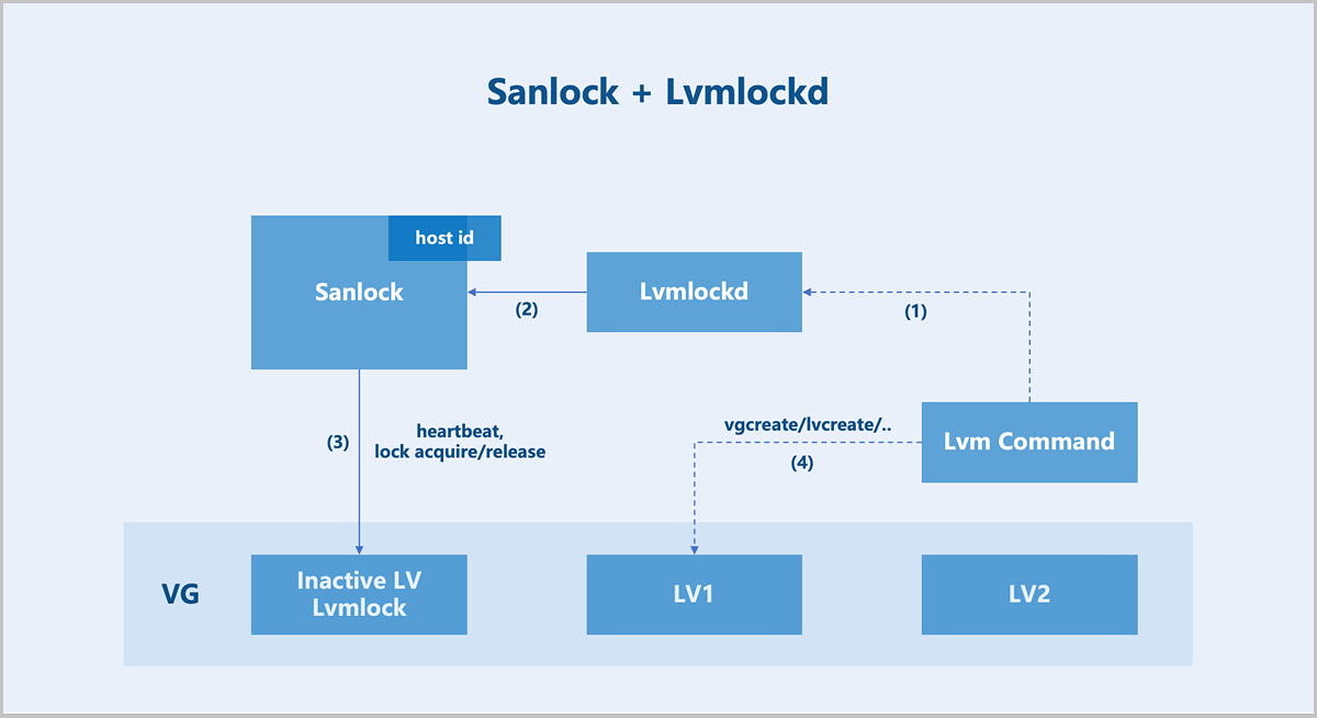
On architecture: In centralized storage, a volume is mapped to a host. Depending on the storage controller's connection method, the multipath service on the host automatically aggregates multiple SCSI devices sharing the same WWID into a multipath device. ZStack ZSphere detects multipath devices with the same WWID across all hosts in the cluster and creates a shared volume group (VG) for the user-selected volume. Logical volumes (LV) are provisioned from this VG, corresponding to volumes, snapshots, and other resources in ZStack ZSphere. To maintain storage cluster consistency, ZStack ZSphere implements a shared storage lock mechanism (Sanlock) for maintaining storage heartbeats, node management, and metadata management.
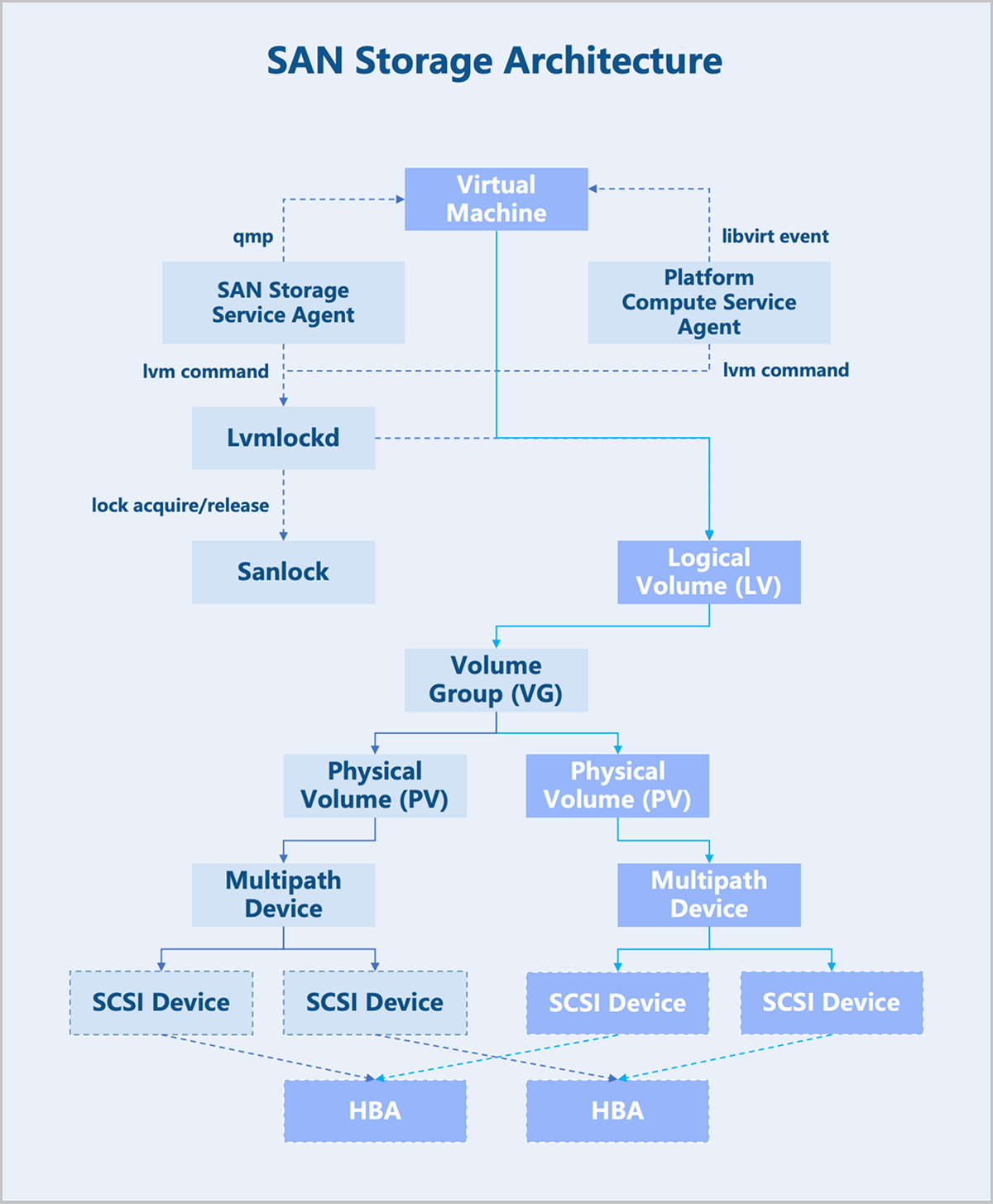
Sanlock + Lvmlockd
Sanlock (Shared storage lock manager) is essentially a lease management mechanism built upon Lamport's algorithms: Delta Paxos and Disk Paxos. This system handles cluster membership management, heartbeat maintenance, arbitration, and message passing. The next step involves translating this lease mechanism into locks usable by LVM: Lvmlockd.
With Sanlock and Lvmlockd, most LVM commands from sever are first sent to Lvmlockd, which translates LVM operations into lock operations recognizable by Sanlock.
Different resource operations require different lock permissions. Resource operations proceed only after obtaining the appropriate locks, ensuring the security of metadata and data. This entire process requires no intermediate node coordination or centralized operations, forming a fully distributed architecture.
Distributed Storage
ZStack ZSphere supports integration with various distributed storage systems. This section primarily introduces the Self-Developed Distributed Storage. It provides comprehensive resource management capabilities for servers, hard disks, data disks, block storage volumes, storage pools, buckets, and more. You can create storage pools with different data redundancy types and configure buckets with specific storage policies and access permissions. This enables rapid and cost-effective deployment of a simple, stable, secure, and highly efficient storage infrastructure.
- Elastic Scalability: Supports horizontal storage expansion. Under the "Internet Plus" trend, emerging services proliferate and data grows exponentially, posing significant challenges to traditional centralized storage. Distributed storage allows cluster capacity and performance upgrades by simply adding new nodes to the cluster.
- High Availability: Supports multiple data redundancy policies, including replication and erasure coding. With replication, you can online adjust the number of replicas in a storage pool. Data is duplicated across multiple nodes, so even if one or several nodes fail, data remains accessible from other nodes, ensuring the availability of the storage cluster. Combined with flexible fault domain policies, the storage service stays reliable even during unexpected events such as hardware failures or network outages.
- Performance Optimization: Optimizes data processing performance through proprietary cache acceleration technology. It utilizes enterprise-grade NVMe SSDs and SATA SSDs to accelerate read and write operations for backend HDD devices, effectively reducing latency and improving the I/O performance of the storage cluster. Furthermore, it employs load balancing technology to evenly distribute storage I/O loads across all nodes, ensuring optimal utilization of system resources.
- Easy Management: Provides a unified, user-friendly management interface and standard RESTful APIs, enabling administrators to easily perform basic lifecycle management and maintenance of physical resources, as well as data operations and recovery tasks.
- High Cost-Effectiveness: Supports deployment on standard hardware, significantly reducing hardware costs. Additionally, elastic scaling capability allows dynamic storage resource adjustment based on business needs, avoiding resource waste and further lowering operational expenses.
- Hardware Layer: Supports standard x86 servers and supports integrating legacy equipments into a shared pool, helping organizations maximize the value of their current IT assets.
- Platform Layer: Copes with the consistent hashing challenges in storage services through a fault domain algorithm. Essentially, this algorithm enhances the basic hash algorithm by incorporating physical deployment logic and cluster state parameters. When cluster data migration occurs, the algorithm minimizes data migration volume based on the actual hardware layout. For example, based on the provided physical topology, the fault domain algorithm can selectively perform migrations within a server or within the same rack/core switch, significantly reducing resource consumption caused by migration. Additionally, the algorithm distributes data based on the cluster state, ensuring full compatibility with different storage devices.
- Data Layer: Uses a proprietary caching technology that leverages enterprise-grade NVMe SSDs and SATA SSDs for read and write caching of backend HDD devices. The technology stores frequently accessed hot data on high-speed SSD devices and dynamically moves cold data to slower HDD devices using an intelligent flushing policy. This approach both enhances the overall performance of the storage cluster and provides massive storage space for upper-layer services.
- Interface Layer: Provides virtual volume devices to operating systems, cloud platform, and databases via the RBD interface.
- Service Layer: Integrates with cloud platforms to deliver cloud infrastructure services.
Data Storage
Cache Acceleration Solution
A cache acceleration solution typically uses SSD-based caching devices to accelerate the data access for HDD data disks. Self-Developed Distributed Storage uses high-speed SSDs through the ZAS cache module to provide I/O caching for traditional HDD devices. The ZAS cache module caches frequently accessed hot data in the high-speed SSD devices and returns it to the application, significantly improving I/O performance, especially in scenarios characterized by hot data access patterns.
The ZAS cache module supports two caching policies: Writethrough and Writeback. In Writethrough mode, data is written simultaneously to the cache and the backend storage device, ensuring data consistency. In Writeback mode, most of the cache is used to buffer write data, ensuring that dirty data is written sequentially to the backend storage device. The system disables the Writeback policy by default but you can switch caching policies at runtime.
- Flexible Cache Data Migration
The ZAS cache module automatically migrates data from slow disks to the SSD cache based on data access frequency and heat to improve access speed for that data. Simultaneously, based on cache usage and available cache space, the module automatically migrates less frequently used data from the SSD cache to slow disks to free up cache space.
- Data Protection
If a data I/O error occurs on the flash device, the ZAS cache module first attempts to read from the disk to recover the data or marks the cache entry as invalid. For unrecoverable errors, such as those involving metadata or dirty data, the cache module automatically disables caching.
Automatic Thin Provisioning
Before data is written to the logical volume, thin provisioning provides upper-layer applications with more virtual storage space than what is physically available in the storage cluster. This offers convenient scalability and improves storage space utilization efficiency.
Storage Pool Recovery QoS
QoS (Quality of Service) is a technology used to address I/O resource allocation issues. It helps you throttle I/O read and write speeds, facilitating the rational allocation of resources.
Within data nodes, an op_shardedwq queue handles various I/O requests from the upper level. This is a composite queue, typically containing several sub-queues. After I/O requests are dequeued, they interact with the disk via the ObjectStore interface. I/O types fall into two main categories: business read/write I/O requests from clients, and I/O generated by internal activities of the storage system, including I/O requests between data nodes, SnapTrim, Scrub, and Recovery.
The Self-Developed Distributed Storage uses a weighted priority queue (wpq) to categorize and store the aforementioned I/O types into corresponding sub-queues. Each priority (prior) queue is created when its first request is enqueued. During dequeue, a weighted probability method determines the prior level. The priority (prior) of each queue serves as its weight. The probability of a prior queue being selected equals the ratio of its priority weight to the total weight of all queues. Even if selected, a prior queue is not guaranteed to dequeue a request; this also depends on the size of the request about to be dequeued.
- Low-Speed Recovery: Low-Speed Recovery gives a higher priority to the business bandwidth. The recovery time is relatively long. Any hardware failures during the recovery may reduce the data security level. We recommend that you choose Low-Speed Recovery in a production environment.
- Medium-Speed Recovery: Mid-Speed Recovery gives the same priority to the business bandwidth and recovery bandwidth. The recovery time is medium. A saturated performance may increase the I/O latency.
- High-Speed Recovery: High-Speed Recovery gives a higher priority to the recovery bandwidth. The recovery time is relatively short. A saturated performance may affect business performance.
Volume Business QoS
The Self-Developed Distributed Storage supports configuring business QoS for block storage volumes, including maximum IOPS and maximum read/write bandwidth. By setting a business QoS, you can control the performance of different block storage volumes to meet diverse business performance requirements.
- The system generates tokens at a fixed rate and places them into a bucket. Every I/O request must acquire a token from this bucket.
- Requests that fail to acquire a token must queue to obtain one, thereby limiting the average data flow rate into the system.
- When the token distribution rate is slower than the token generation rate, tokens can accumulate in the bucket. This allows direct consumption of tokens from the bucket during short-term traffic bursts.

Data Protection
Volume Snapshot Protection
Snapshots serve as an important data protection mechanism in the Self-Developed Distributed Storage. Snapshots allow users to create a complete state copy of a block storage volume at a specific point in time without interrupting services or impacting the production environment.
Snapshot Creation
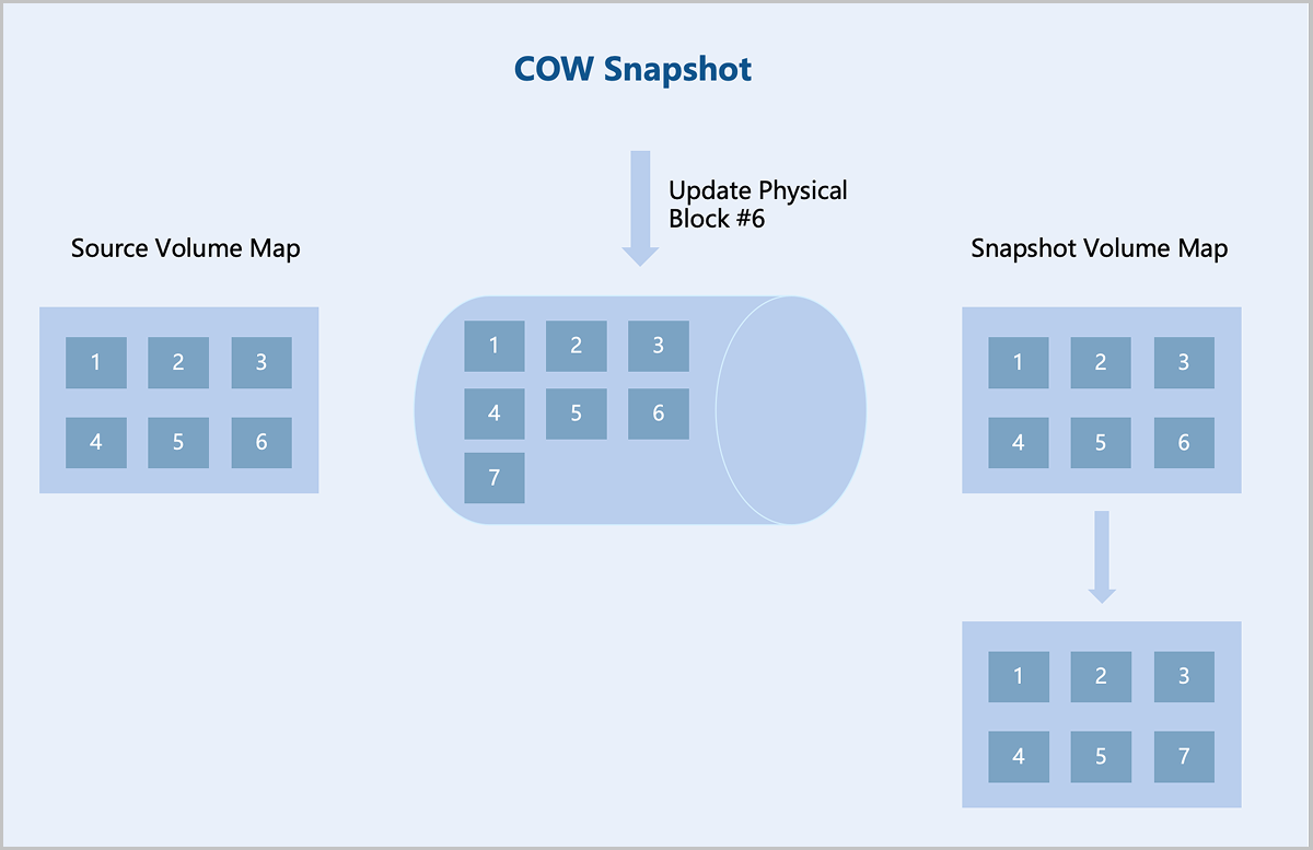
The Self-Developed Distributed Storage uses a COW (Copy-On-Write) snapshot technology. After creating a COW snapshot, the system creates a read-only copy of the original block device within the storage cluster. Data blocks are duplicated only when modifications occur in either the original device or the snapshot. This preserves the state of the original data in the snapshot while avoiding unnecessary data redundancy. The system also records the relationship between the original block device and the snapshot, as well as metadata information for each snapshot, such as creation time, size, and parent snapshot. Recording this metadata enables the system to accurately locate the specific snapshot state during data recovery.
Data Rollback and Recovery
The Self-Developed Distributed Storage supports creating new block storage volumes from snapshots, also known as cloning, where the new volume starts from the state of a specific snapshot. Additionally, in backup recovery or data rollback scenarios, you can revert a block storage volume to the state of a specified snapshot.
Data Redundancy
Overview
Data redundancy is the cornerstone for storage systems to achieve high availability, data protection, and business continuity. Faced with increasing data volumes, complex application scenarios, and potential risks such as hardware failures, network interruptions, and human errors, appropriate data redundancy policies provide you with a robust data protection barrier, ensuring business continuity and maximizing data value. This section briefly compares the characteristics of redundancy techniques in centralized storage and distributed storage, followed by a detailed explanation of the two core data protection policies adopted by the Self-Developed Distributed Storage: replication and erasure coding (EC).
Centralized Storage vs. Distributed Storage
Centralized Storage
Traditional centralized storage uses controllers and disk enclosures to provide data management and read/write capabilities. It typically employs dual controllers for redundancy, while some high-end storage uses multiple controllers. Storage space is provided through the controller's built-in drive bays or externally connected expansion enclosures. Traditional centralized storage commonly uses RAID to protect data, such as RAID 5, RAID 6, or RAID 10.
Distributed Storage
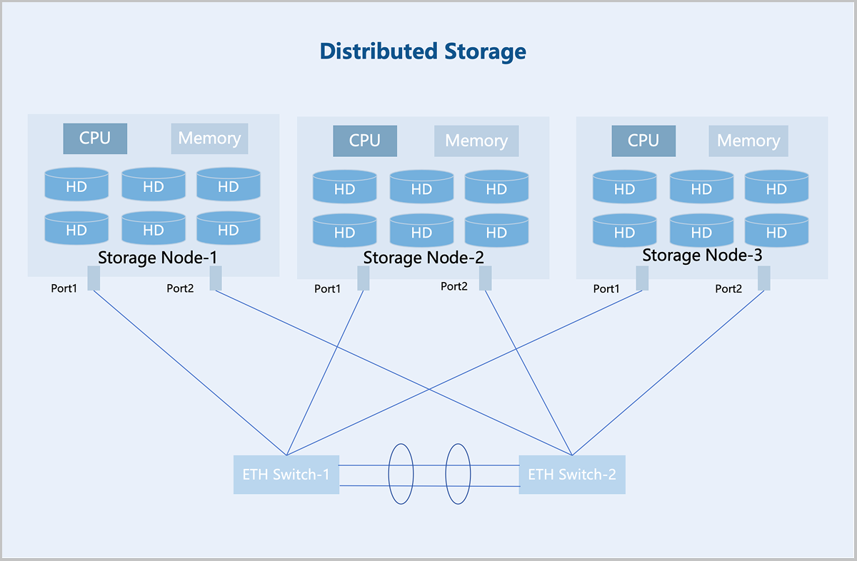
Distributed storage adopts a decentralized architecture where each storage node provides computing and storage resources, enabling more flexible scalability and larger storage capacity. Storage nodes are interconnected via standard Ethernet switches and managed by the distributed storage software to provide a unified storage resource pool to upper-layer services. Furthermore, distributed storage supports horizontal scaling. A single cluster can expand to thousands of nodes to provide EB-level capacity, making it suitable for massive data storage scenarios.
Centralized Storage vs. Distributed Storage
- Cross-Node Redundancy: Distributed storage supports redundancy across multiple nodes. For example, a three-replica policy can tolerate two nodes to fail simultaneously without data loss, whereas RAID only provides redundancy within a single node.
- Global Hot Spares and Data Recovery: Unlike RAID, which relies on the dedicated hot spare disk, distributed storage uses all available disks for data recovery, significantly improving efficiency. Additionally, distributed storage requires no additional hardware support, whereas RAID typically needs a dedicated RAID card.
Replication
Definition
Replication is a data protection technique that achieves data redundancy and high availability by storing the copies of the same data across different nodes. If a node fails, data can be recovered from the replicas on other nodes. You can configure 2 to 6 replicas, with 3 replicas recommended for production environments.
- Read/Write in Normal State
Taking a 3 replicas at the server level as an example: During data write, the system copies the data into three identical replicas and stores each on data disks in three different servers. During data read, the system reads the data from any one of the servers and returns it to the user.
图 3. Read/Write in Normal State with Three Replicas 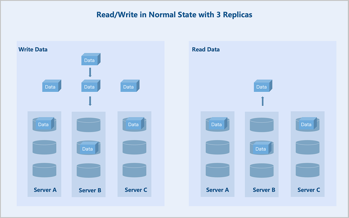
- Read/Write Under Failures
Taking a 3 replicas at the server level as an example: If server C fails, the system stores replicas on the remaining two servers. During data read, the system reads one replica from either of the remaining two servers and returns it to the user.
图 4. Read/Write Under Failures with Three Replicas 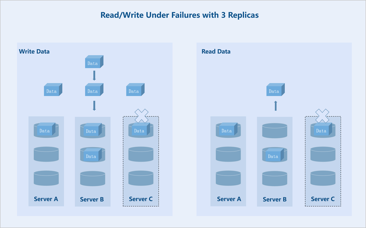
Erasure Coding (EC)
Overview
- Standard EC (K+M): K indicates the number of data blocks, and M indicates the number of parity blocks. This configuration tolerates simultaneous failures of M fault domains without affecting data availability.
- Folded EC (K+M:B): K indicates the number of data blocks, and M:B indicates the number of parity blocks. This configuration tolerates simultaneous failures of M hard disks or B fault domains without affecting data availability.
Policy Types
| EC Policy | Storage Efficiency | |
|---|---|---|
| Recommended Values | 2+1 | 66.67% |
| 4+2 | 66.67% | |
| 8+3 | 72.73% | |
| 4+2:1 | 66.67% | |
| 8+2:1 | 80.00% | |
| 16+2:1 | 88.89% | |
| Custom | K/(K+M) | |
Standard EC
- Read/Write in Normal State
Standard EC (K+M): Taking a server-level 4+2 EC policy as an example: During data write, the system splits the data into 4 equally sized data blocks and generates 2 parity blocks of the same size through the parity algorithm. The system randomly stores these 6 blocks across 6 servers. If any 2 servers fail, data remains accessible. During data read, the system reads data blocks from different data disks on 4 servers, assembles the 4 data blocks into complete data, and returns it to the user.
图 5. Data Write in Normal State with EC (4+2) 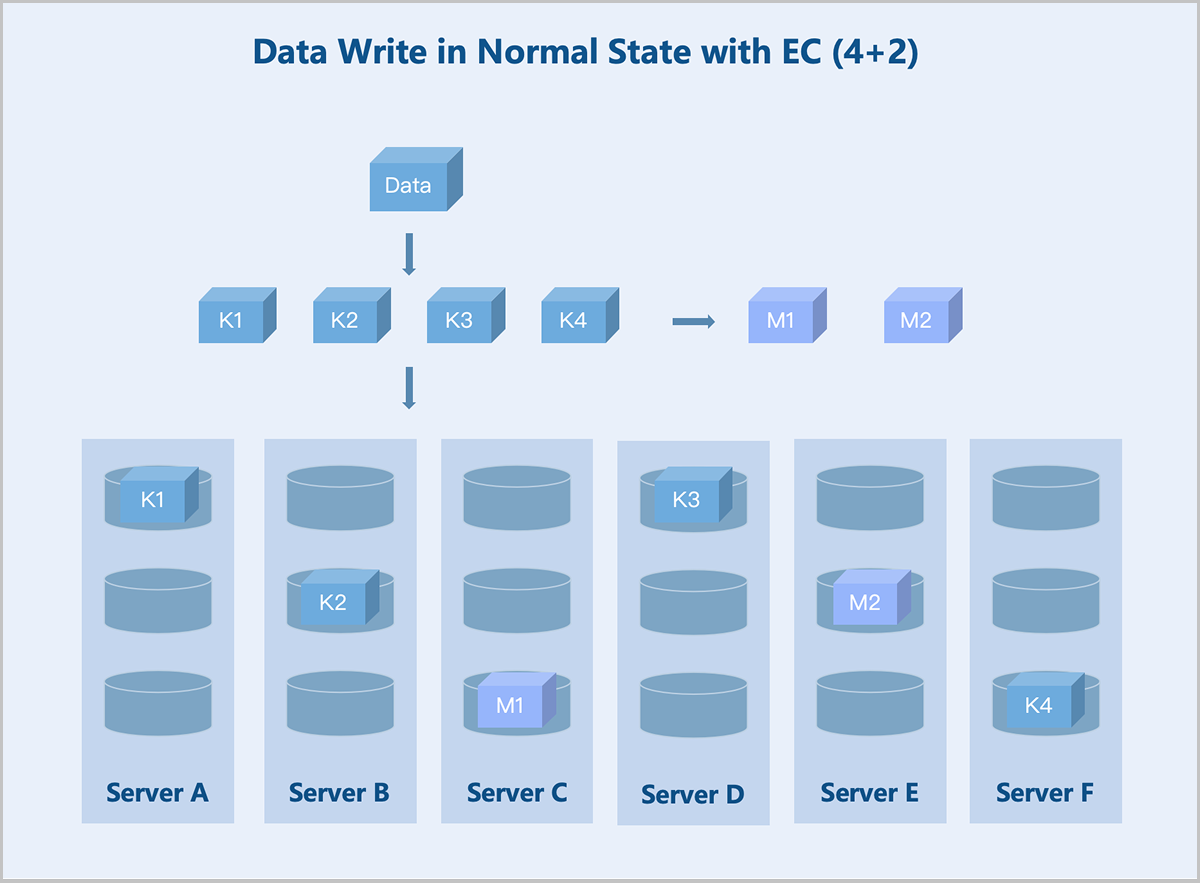
图 6. Data Read in Normal State with EC (4+2) 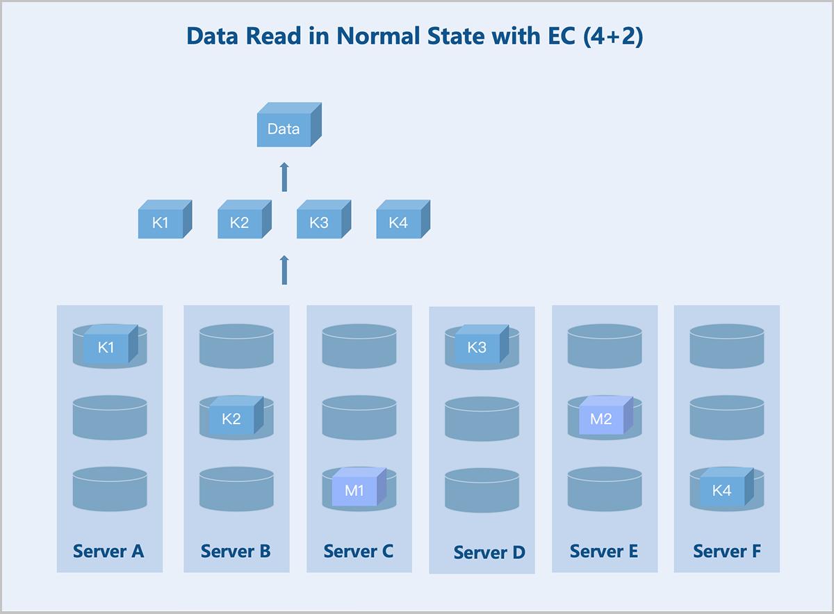
- Read/Write Under Failures
Standard EC (K+M): Taking a server-level 4+2 EC policy as an example: If the number of available servers drops below K+M due to failures, the system stores newly written data on the remaining servers before the recovery. This ensures I/O continuity without reducing the reliability. Once the failed servers recover, the data redundancy policy reverts to K+M. During data read, the system reads data from the remaining healthy servers and recovers the data using the parity algorithm before returning it to the user.
图 7. Data Write Under Failures with EC (4+2) 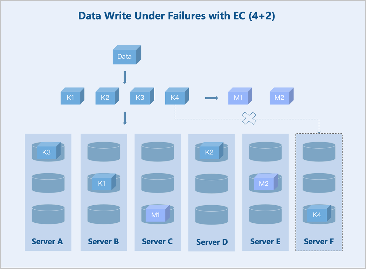
图 8. Data Read Under Failures with EC (4+2) 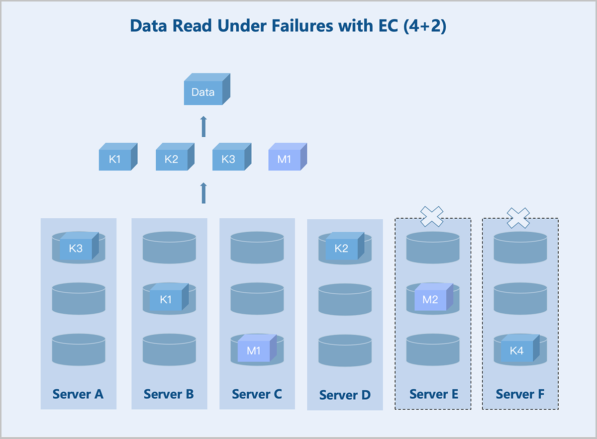
Folded EC
Folded EC, also known as sub-node EC, is another common data redundancy technique. Unlike the standard K+M EC configuration, the folded EC typically follows a K+M:B format, where B is usually set to 1. The folded EC maintains high data reliability while delivering improved storage efficiency.
For example, while a standard EC requires a minimum of 6 nodes, as its smallest fault domain is the storage node. A folded EC with 4+2:1 configuration can achieve data redundancy with as few as 3 storage nodes.
Furthermore, the folded EC supports scaling in and out just like standard EC. You can converts a folded EC to a standard EC as long as the fault domain requirements are met.
- Read/Write in Normal State
Folded EC (K+M:B): Taking a server-level 4+2:1 EC policy as an example: During data write, the system splits the data into 4 equally sized data blocks and generates 2 parity blocks of the same size through the parity algorithm. The system randomly stores these 6 blocks across 5 servers. If any one server fails, data remains accessible. During data read, the system reads data blocks from different data disks on 3 servers, assembles the 4 data blocks into complete data, and returns it to the user.
图 9. Data Write in Normal State with EC (4+2:1) 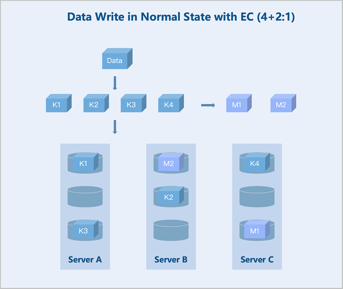
图 10. Data Read in Normal State with EC (4+2:1) 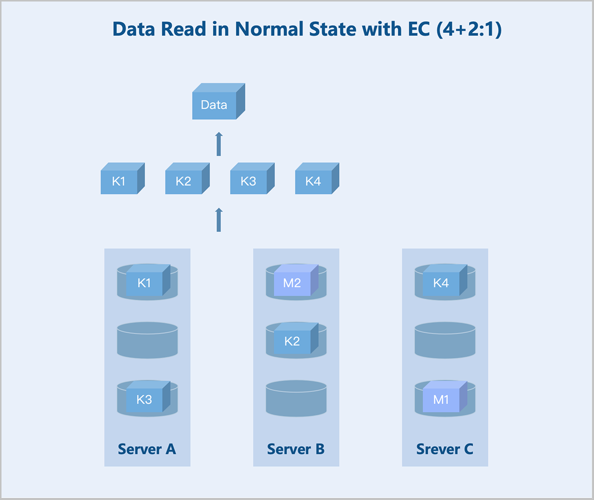
- Read/Write Under Failures
Folded EC (K+M:B): Taking a server-level 4+2:1 EC policy as an example: If one server or M hard disks fail, the system continues writing data and parity blocks to the remaining healthy servers according to the K+M configuration. During data read, the system reads data from other healthy servers and recovers the data using the parity algorithm before returning it to the user.
图 11. Data Read Under Failures with EC (4+2:1) 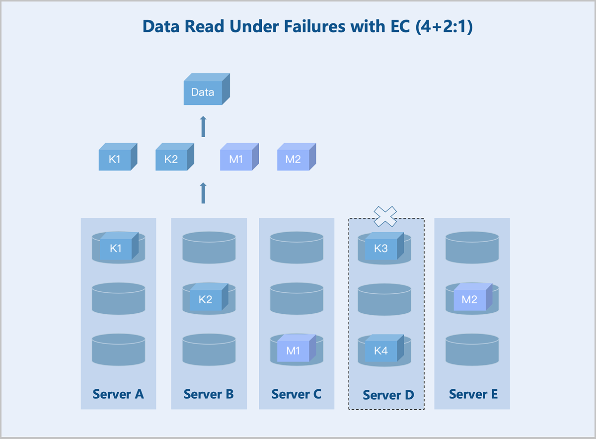
Replication vs. EC
- Storage Efficiency: EC holds a significant advantage. For example, a 4+2 EC policy offers approximately 66% effective storage, while 3 replicas policy achieves only 33.3%.
- Read/Write Performance: Performance varies significantly in small I/O scenarios. The gap narrows in large I/O scenarios. EC involves data validation during writes, which may introduce write amplification. During reads, performance can be impacted if any of the multiple nodes encountered high latency. In contrast, replication only needs to read one complete copy without any data reassembly
- Rebuild Performance: Replication generally outperformed EC in rebuild speed. Replication involves simple data copying without validation, resulting in faster rebuilds. EC rebuild requires reverse parity calculation, demanding more data I/O and higher CPU consumption.
- Fault Tolerance: Both policies have strengths and weaknesses. Replication allows up to (number of replicas − 1) simultaneous non-monitoring nodes failures without data loss. For EC, a 4+2 policy allows 2 simultaneous non-monitoring nodes failures without data loss.
Fault Domain Isolation
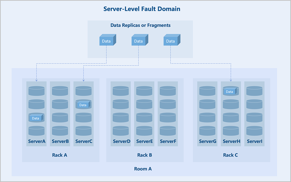
- Server-Level: Each server in the cluster acts as a fault domain. Different replicas or blocks of data are stored on different servers.
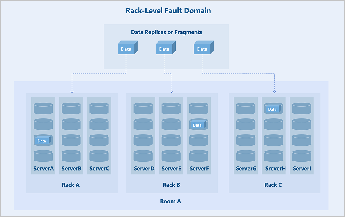
- Rack-Level: Each rack in the cluster acts as a fault domain. Different replicas or blocks of data are stored in different racks. Recommended for clusters of larger scale with more racks.
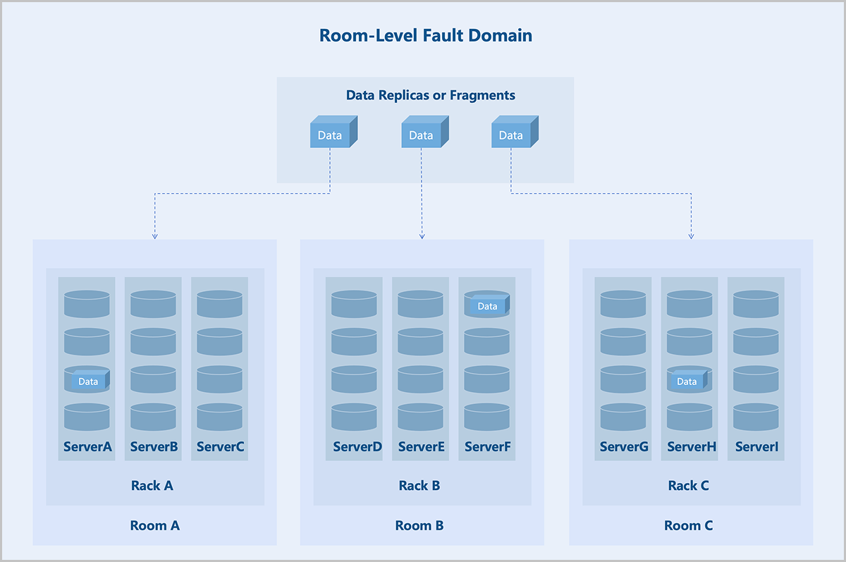
- Room-Level: Each room in the cluster acts as a fault domain. Different replicas or blocks of data are stored in different rooms. Recommended for very large clusters spanning multiple rooms.
Fault domain isolation helps contain the impact of failures to a specific scope, preventing a domino effect and thereby enhancing business continuity.
By leveraging fault domain-aware scaling along with rational storage policies, newly added nodes can form an independent disk pool without requiring data migration. This enables seamless capacity expansion, shielding applications from underlying storage changes and eliminating the need for application-level adjustments traditionally associated with storage updates. As a result, both operational and administrative workloads are significantly reduced, while system reliability and performance are enhanced.
Data Consistency Check
- Scrub Check: Focuses on metadata. It completes quickly and runs frequently. It is recommended to perform Scrub daily. You can customize the schedule.
- Deep-Scrub Check: Focuses on data. It takes longer to complete and may impact I/O performance. It is recommended to run during off-peak hours. An alert is triggered if no Deep-Scrub has been completed within 30 days.
Cluster Hardware Topology
The cluster topology provides a visual representation of the actual deployment of the cluster's physical resources. The topology includes logical entities such as data centers, rooms, racks, and servers, organized hierarchically in a tree structure to illustrate the distribution relationship from rooms down to servers. Each tree structure has a root node, and the cluster topology supports multiple root nodes. After planning the topology, you can select the corresponding level of data redundancy policy when creating a storage pool.
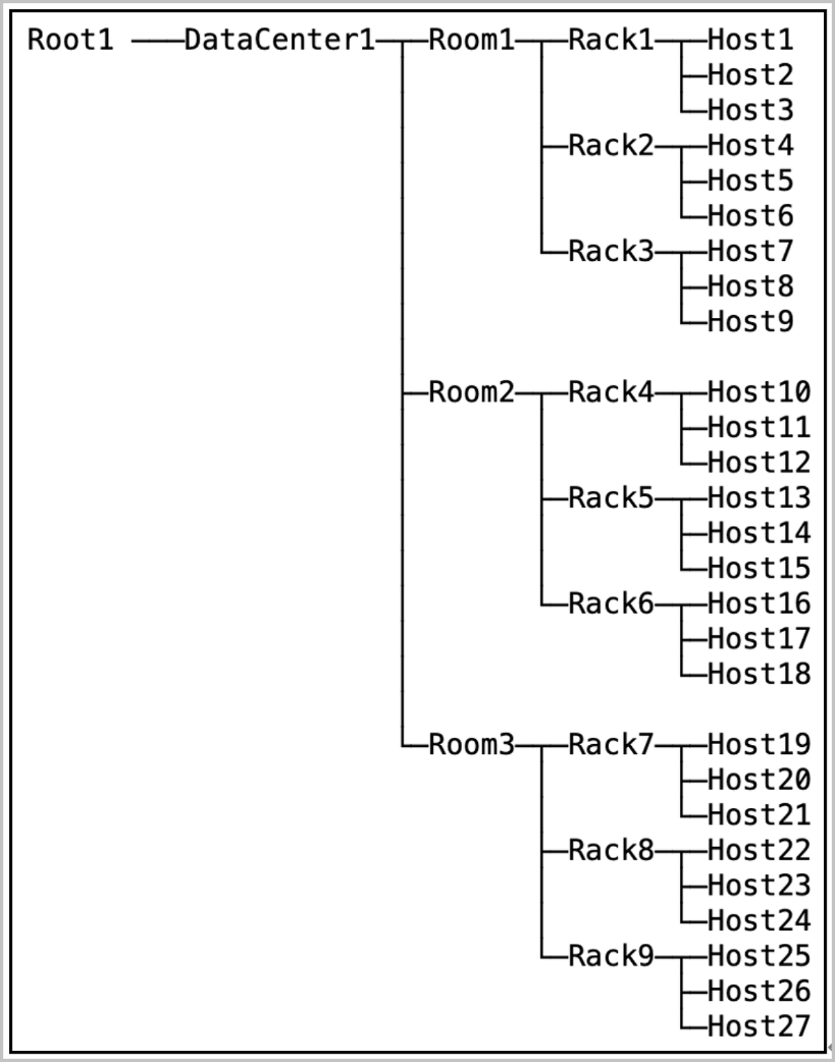
| Topology Object | Quantity Range |
|---|---|
| Data Center | 0~2 |
| Room | 0~100 (Per Data Center) |
| Rack | 0~100 (Per Room) |
| Server | 0~20 (Per Rack) |
Convenient O&M
Multiple Resource Pools
The Self-Developed Distributed Storage supports multiple resource pools, helping you utilize storage media with different performance characteristics and achieve fault isolation.
Each resource pool has distinct attributes and performance, such as the number of replicas, data redundancy level, and storage media. You can flexibly allocate and manage resources based on actual requirements to improve storage efficiency and performance.
Resource pools are isolated from each other. You can implement data isolation management across multiple pools. Besides, failures in a single resource pool does not affect other resource pools, effectively safeguarding data security and storage reliability.
Hard Disk Light
The Self-Developed Distributed Storage provides a visual interface to light on the hard disk for rapid locating. When you need to maintain or replace a disk, click Disk Light in the UI. The corresponding disk's LED indicator lights up in the physical environment, guiding you to quickly and accurately identify the device, thereby improving O&M efficiency.
Disk S.M.A.R.T. Monitoring
The Self-Developed Distributed Storage supports S.M.A.R.T. (Self-Monitoring, Analysis, and Reporting Technology) monitoring to track the health status, temperature, firmware, and total bytes written of disks. Upper-layer services trigger relevant alerts based on I/O errors and disk status information returned by the S.M.A.R.T. data.
Data Disk Maintenance Mode
The Self-Developed Distributed Storage supports maintenance mode for data disks. To maintain servers or disks, you can put the corresponding disks into maintenance mode on the UI. A disk in this mode stops all services and data access, and the data on the disk does not undergo rebalancing.
Automatic Failure Detection and Alerting
The Self-Developed Distributed Storage supports automatic failure detection and alerting. This mechanism monitors the storage platform system and individual storage servers. Upon detecting a failure, the system automatically sends alert messages to the platform. You can also add email endpoints to receive alarms, enabling timely response and recovery.
When a failure occurs, the system supports automatic service restart and data migration. This maximizes data reliability and availability, forming a highly reliable and highly available distributed storage system.
Data Rebalancing
The Self-Developed Distributed Storage supports data rebalancing to evenly distribute data across data disks under all storage servers in the cluster. This enhances storage system performance and reliability.
- Based on storage pool configurations and storage server load, the system automatically migrates data from overloaded nodes to those with lower load to achieve load balancing.
- When a server fails or a new server is added, the system automatically migrates data to maintain consistency and reliability.
Manual Data Rebalancing:
The system also supports manual data rebalancing. You can manually initiate rebalancing operations based on the actual data distribution.
Network Virtualization
Overview
Network virtualization is a technology that abstracts network capabilities away from dedicated network hardware. The underlying hardware only needs to provide basic packet forwarding services. Network virtualization provides various network services, including data switching, routing, security groups, and more, achieving an experience comparable to a physical network.
ZStack ZSphere abstracts the network model into distributed switches and distributed port groups. A distributed switch spans multiple hosts within a data center, providing the ability to deploy, manage, and monitor virtual networks across the entire data center. A distributed port group is a collection of virtual ports on a distributed switch. Virtual machines in the same port group share a uniform network configuration. This enables virtual machines to migrate between different hosts. Additionally, the platform provides a distributed DHCP service on distributed port groups. You can also configure DNS for virtual machines. These features meet the requirements of different network scenarios in the data center.
Key Features
Distributed Switch
Switches identify hosts using MAC addresses or IP addresses to forward and control network traffic between hosts, and between hosts and external networks. In traditional data centers, host locations are fixed, and positional relationship between switches and hosts remain constant, meaning switch configurations rarely require changes.
- You cannot pre-determine virtual machine MAC addresses or IP addresses in advance.
- During virtual machine migration, the VM configuration on physical switch ports also needs to migrate, which may cause migration failures.
- When source and destination virtual machines are on the same host, network traffic might bypass the switch, preventing the switch from performing traffic control.
ZStack ZSphere introduces distributed switches that provide traffic forwarding and control between virtual machines, and between virtual machines and external networks, offering you convenient, flexible, and feature-rich network capabilities.
- The virtual switch forwards network traffic based on MAC addresses.
- Virtual machine NICs connect virtual machines to the virtual switch, providing data channels for virtual machine traffic.
- Host NICs serve as uplink ports for the virtual switch, forwarding cross-host virtual machine traffic to physical switches.
Security Group
In traditional data centers, networks divide into trusted zones, DMZ zones, and untrusted zones. Perimeter firewalls enforce traffic control to ensure network security. In virtualized data centers, perimeter firewalls may struggle to handle scenarios such as network isolation between different tenants and access control between different services within the same tenant flexibly. Therefore, ZStack ZSphere introduces a new component: security group. A security group is a distributed firewall focused on controlling east-west traffic and supports inbound and outbound traffic control at the virtual machine NIC level.
- The set of security group rules: supports the addition, deletion, and modification of rules to control rule actions.
- The set of associated NICs: supports the binding of virtual machine NICs to apply security group rules to them.
- Default policies: If no rules are added, except communication between group members, the security group denies all inbound traffic by default, and allows all outbound traffic.
- Rule flexibility: Rules support on-demand modification, including source IP, destination IP, destination port, protocol type, and priority.
- Dynamic priority adjustment: When adding a rule, you can insert it at a specific priority. When removing a rule, priorities automatically adjust to remain consecutive.
- Multiple security groups per NIC: A virtual machine NIC supports associating to multiple security groups. You can dynamically adjust the priority of these groups. By default, rules in the first-associated security group take effect first.
How It Works
- Composition of a security group:
- Source: Supports source data (for inbound direction) and destination data (for outbound direction).
- Address Type: Supports IPv4 and IPv6.
- Protocol Type and Port: Supports ICMP, TCP, UDP, and more.
- Action: Deny or allow.
- Priority of security group rules:
- Rule priority is a consecutive and unique (priority 0 indicates the highest priority by default). Lower priority numbers indicate higher precedence.
- By default, newly added rules have the lowest priority. When inserting a rule at a specified priority, subsequent rule priorities adjust automatically to ensure uniqueness.
- When traffic passes through a virtual machine NIC, matching starts from the rule with the highest priority. If a match succeeds, the rule action executes. Otherwise, matching continues with the next rule.
- Import and export of security group rules:
- Existing rules support one-click export.
- Exported rules supports re-importing into other security groups with rule validation provided during import.
- Associating multiple security groups to a NIC:
- A virtual machine NIC allows associating to multiple security groups. The associated groups support priority ordering. A lower number indicates a higher group priority.
- When traffic passes through the virtual machine NIC, matching starts from the security group with the highest priority. If a rule within that group match succeeds, the rule action executes. Otherwise, matching proceeds to the next security group.
- NIC default policy:
- By default, the NIC's default inbound policy is Allow, and the default outbound policy is Deny. These default policies support modification.
- When traffic does not match any security group rule, the NIC's default policy executes.
Applications
- Access control among different businesses.Take a typical web application as an example.
- Allow any IP address to access TCP ports 80 and 443 on the Web virtual machines.
- Allow the Web virtual machines to access TCP port 8080 on the App virtual machines.
- Allow the App virtual machines to access TCP port 3306 on the DB virtual machines.
Create separate security groups for the three business types (Web, App, DB) and configure corresponding rules to achieve access control among the different businesses.
图 1. Access Control for Different Businesses 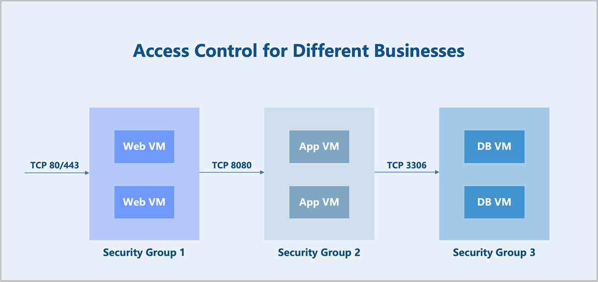
- Coexistence of multiple businesses.In addition to providing service capabilities, the above business virtual machines also need to allow operational control (assumed to use the SSH protocol). There are two implementation options:
- Option 1: Add a new rule to each of the three security groups.
- Option 2: Create a new security group and associate it to the NICs of all the above business virtual machines.
ZStack ZSphere supports associating multiple security groups to a virtual machine NIC. Option 2 is the preferred method for its better flexibility and controllability. You can configure two security groups for each business virtual machine NIC mentioned above and adjust the security group priority and default rules as needed.
- Disabling communication within a security group.
By default, virtual machines within the same security group can communicate with each other without any rule restrictions. In certain scenarios where communication between virtual machines within the same group must be prohibited, you can disable the default rule: Allow for communication within the group. Note that this default rule cannot be deleted.
Virtual Resources Management
Virtual Machine Management
VM Scheduling Policy
A VM scheduling policy is a resource orchestration policy based on which virtual machines are assigned hosts to achieve the high performance and high availability of businesses. You can add virtual machines to a VM scheduling group and associate a scheduling policy to this group to implement VM scheduling.
Function Principles
- If a mutually exclusive virtual machine or aggregated virtual machine policy is bound, no host scheduling group needs to be specified, and the virtual machine is assigned to a host according to the policy and its execution mechanism.
- If a virtual machine host affinity or virtual machine mutually exclusive host scheduling policy is bound, the corresponding host scheduling group must be specified, and the virtual machine is assigned to a host according to the policy and its execution mechanism.
The following explains the working principles of the four types of scheduling policies through four scenarios:
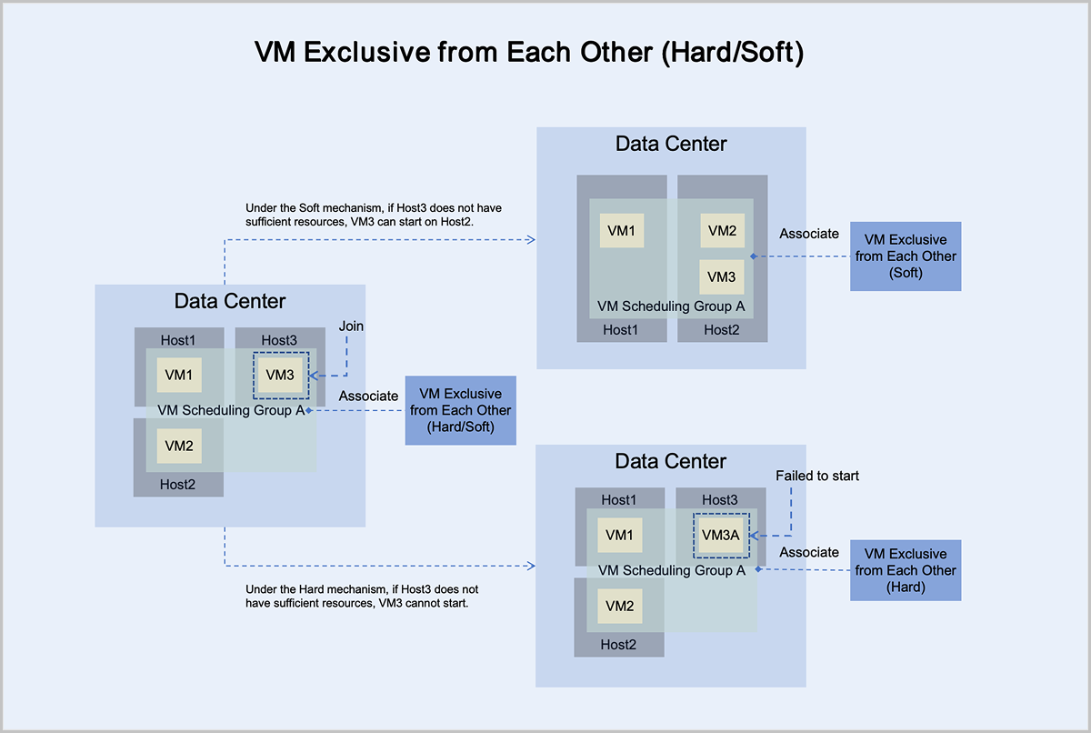
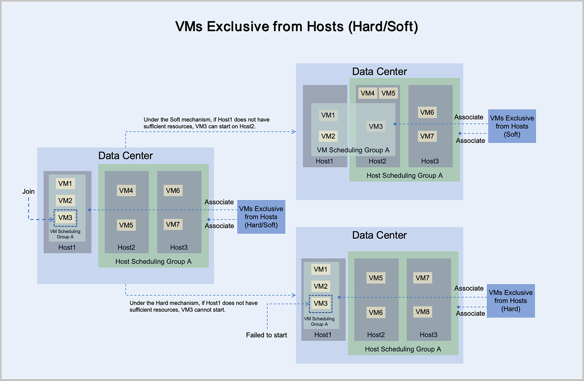
- Under the mandatory mechanism, virtual machine VM3 adheres to the principle
of mandatory mutual exclusion with other virtual machines in the group:
- If Host3 has sufficient resources, it can normally start and run on Host3.
- If Host3 does not have sufficient resources, it cannot start on Host3.
- Under the preferred mechanism, virtual machine VM3 adheres to the principle
of trying to mutually exclude other virtual machines in the group,
prioritizing starting on Host3:
- If Host3 has sufficient resources, it can normally start and run on Host3.
- If Host3 does not have sufficient resources, VM3 can attempt to start on another host with sufficient resources. In this scenario, VM3 starts and runs on Host2.
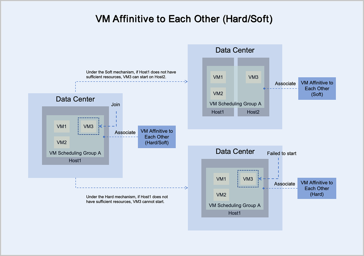
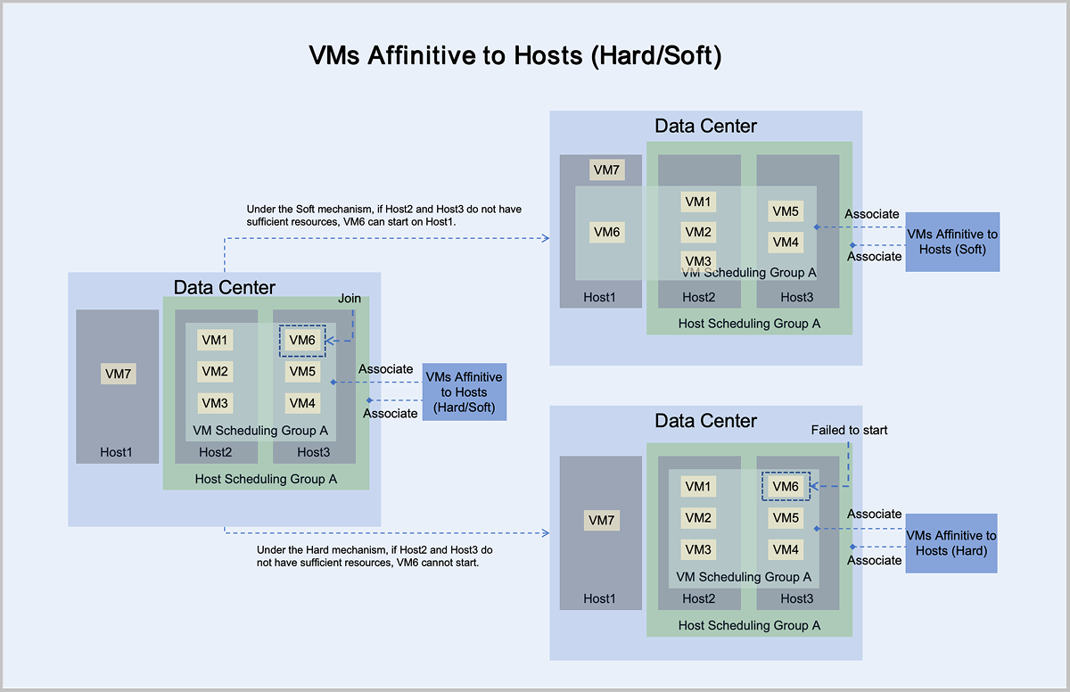
- Under the mandatory mechanism, virtual machine VM3 adheres to the principle
of mandatory aggregation with other virtual machines in the group:
- If Host1 has sufficient resources, it can normally start and run on Host1.
- If Host1 does not have sufficient resources, it cannot start on Host1.
- Under the preferred mechanism, virtual machine VM3 adheres to the principle
of trying to aggregate with other virtual machines in the group,
prioritizing starting on Host1:
- If Host1 has sufficient resources, it can normally start and run on Host1.
- If Host1 does not have sufficient resources, VM3 can attempt to start on another host with sufficient resources. In this scenario, VM3 starts and runs on Host2.
- Under the mandatory mechanism, virtual machine VM3 adheres to the principle of mandatory mutual exclusion with hosts in host scheduling group A:
- If Host1 has sufficient resources, it can normally start and run on Host1.
- If Host1 does not have sufficient resources, it cannot start on Host1.
- Under the preferred mechanism, virtual machine VM3 adheres to the principle of trying to mutually exclude hosts in host scheduling group A, prioritizing starting on Host1:
- If Host1 has sufficient resources, it can normally start and run on Host1.
- If Host1 does not have sufficient resources, VM3 can attempt to start on another host with sufficient resources. In this scenario, VM3 starts and runs on Host2.
- Under the mandatory mechanism, virtual machine VM6 adheres to the principle of mandatory aggregation with hosts in host scheduling group A:
- If Host2 or Host3 has sufficient resources, it can normally start and run on Host2 or Host3.
- If Host2 and Host3 do not have sufficient resources, it cannot start on Host2 or Host3.
- Under the preferred mechanism, virtual machine VM6 adheres to the principle of trying to aggregate with hosts in host scheduling group A, prioritizing starting on Host2 or Host3:
- If Host2 or Host3 has sufficient resources, it can normally start and run on Host2 or Host3.
- If Host2 and Host3 do not have sufficient resources, VM6 can attempt to start on another host with sufficient resources. In this scenario, VM6 starts and runs on Host1.
Virtual Machine Clone
ZStack ZSphere provides two cloning methods to meet different service needs: full clone and instant full clone.
Full Clone
Full clones do not share data with the source VM. Instead, full clones create a new virtual machine by first converting the source VM into an image file. The source VM image is a complete file containing all necessary files and configurations for the VM and is stored in the image storage. This image file is then pushed to the data storage to serve as an image cache for the cloned virtual machine, thereby creating a new virtual machine. Full cloned VMs are not restricted by the data storage. The cloned VMs can be configured to start on a data storage different from that of the source VM.
Full clone virtual machines are completely isolated from and independent of the source VM. This independence ensures that the new VM's performance is in no way affected. Full clones typically require more storage. However, ZStack ZSphere optimizes storage during batch full cloning operations. The image cache for new VMs is stored only once on the data storage. This avoids excessive consumption of data storage resources and also accelerates the startup of batch-cloned virtual machines.
Instant Full Clone
When you perform instant full cloning, the process initially uses linked cloning technology to create a new VM that depends on the source VM, ensuring fast VM provisioning. Subsequently, a background task initiates a snapshot merge operation that completely separates the cloned VM's data from the source VM. As a result, VMs created through fast full cloning benefit from rapid boot times and ultimately achieve complete data independence, with no performance impact after the cloning process completes.
Bare Metal Management
- Management Network: Manages hardware resources on ZStack ZSphere.
- Distributed Port Group: Serves as the service network for bare metal instances to provide application services.
- IPMI Network: Used by the management node to perform remote operations on bare metal chassis and bare metal instances, such as powering on/off, rebooting, and retrieving hardware information.
- Deployment Network: Used by the PXE sever to assign IP addresses via the DHCP service and to transfer images via the TFTP service.
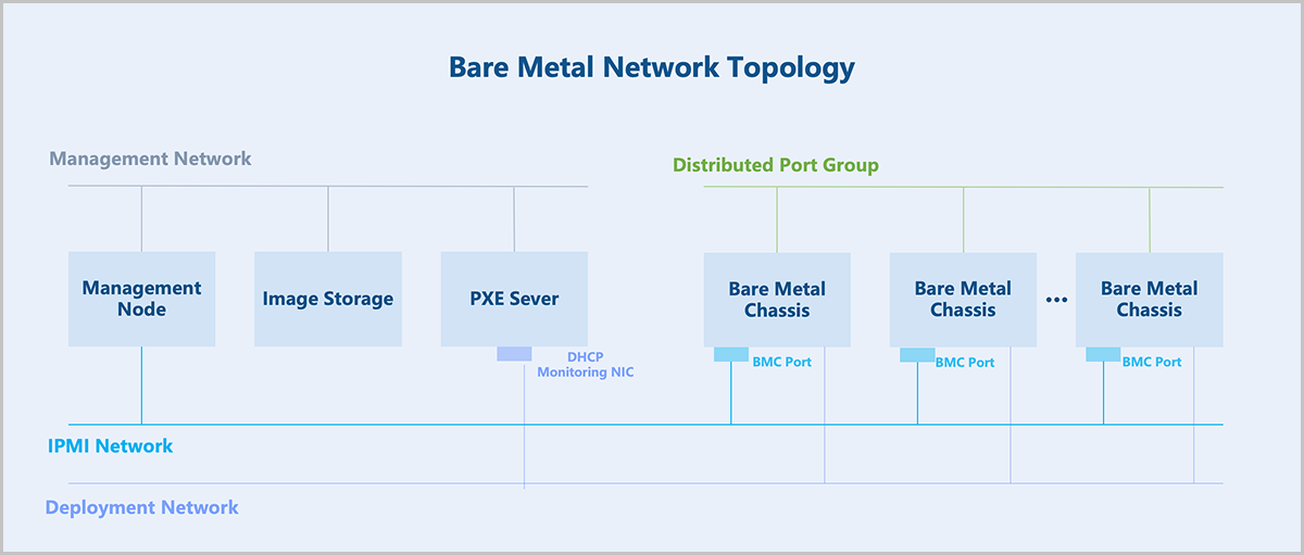
The core of the bare metal management: hardware information retrieval and unattended deployment of bare metal chassis.
- The management node directs the bare metal chassis to perform a PXE boot via the PXE server.
- The PXE server encapsulates DHCP, TFTP, and image storage services. After the bare metal chassis boots via PXE, it obtains an IP address through DHCP, downloads pxelinux.0 and boot files from the TFTP server, loads the kernel into memory for execution, and boots into a LiveCD system.
- In the LiveCD system, a detection script runs and reports the hardware information of the bare metal chassis back to the management node.
- Based on the returned hardware information, a preconfigured template is applied to the bare metal chassis. This template includes partition information, NIC bonding, IP address, and more.
- Select an OS ISO for installation to deploy the bare metal instance.
- The bare metal chassis is rebooted for a PXE boot. The PXE server pre-downloads the target OS ISO, and the bare metal chassis performs an unattended deployment according to the preconfigured template. After deployment, the chassis automatically configures the NIC and other settings based on the preconfigured template, completing the bare metal instance configuration.
- For better O&M of bare metal instances, the PXE server supports deploying a bare metal monitoring service. This service enables real-time monitoring of internal data within the bare metal instances, including metrics for CPU, memory, disk capacity, disk I/O, NICs, and more.