VM Instance
What is VM Instance?
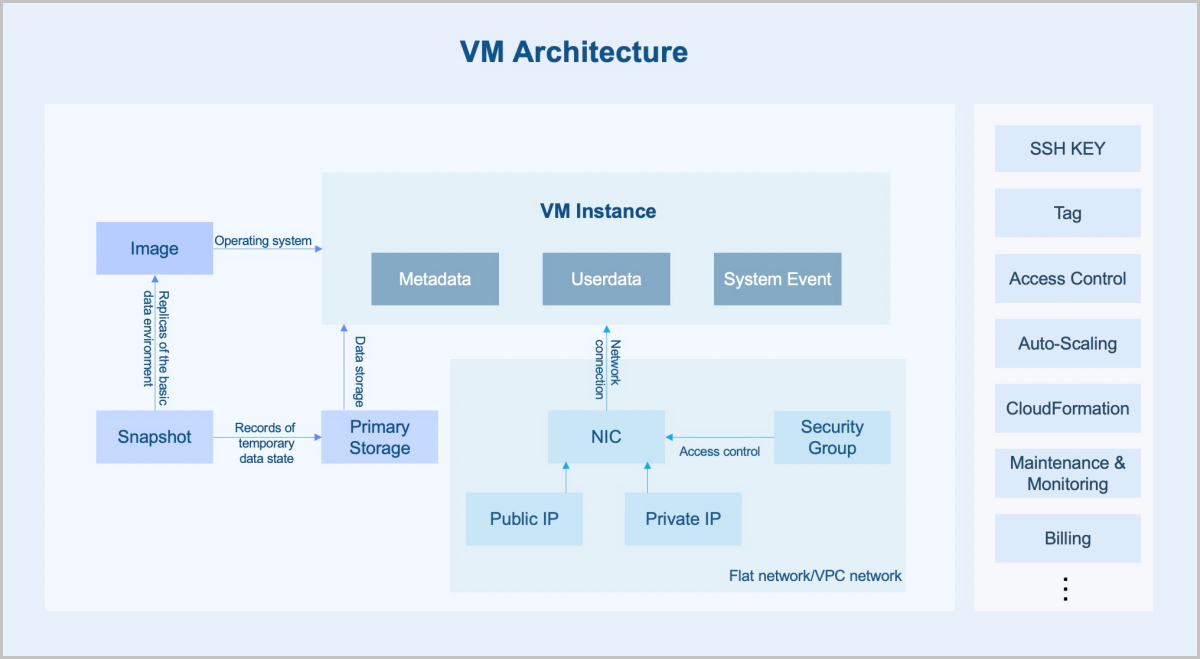
A VM instance is a virtual machine instance running on a host. A VM instance has its own IP address and can access public networks and run application services. ZStack Cube Ultimate supports more than 60 VM instances per host.
Architecture
- Instance: A virtual machine instance running on a host. An instance includes the basic resources such as CPU, memory, operating system, network configurations, and disks.
- Image: An image is a template file used to create a VM instance. Images provide the operating system required by a VM instance.
- Primary storage: A primary storage is one or more servers that store volume files of VM instances. These files include root volume snapshots, data volume snapshots, image caches, root volumes, and data volumes.
- Snapshot: A snapshot is a point-in-time capture of data status in a volume. Before you perform a business-sensitive operation on a VM instance, you can schedule snapshot creation at specified time points to record the state of the VM data. This allows rollback in case of breakdowns.
- Networks:
- Flat network: A flat network is connected to the network where the host is located and has direct access to the Internet. VM instances in a flat network can access public networks by using elastic IP addresses.
- VPC network: A VPC network is a private network where VM instances can be created. A VM instance in a VPC network can access the Internet through a VPC vRouter.
- Security group: A security group provides security control services for VM NICs. It filters the ingress or egress TCP, UDP, and ICMP packets of VM NICs based on the specified security rules.
Characteristics
- High availability (HA): You can set an HA mode for a VM instance. When the VM instance is stopped due to exceptions, the HA policy can trigger the automatic restart of the VM instance to improve the VM availability.
- Security:
- The VM console allows you to conveniently monitor and manage VM instances. Note that you must have the corresponding permissions before you can log in to the VM console.
- A VM instance supports IP/MAC/ARP anti-spoofing. Abnormal protocol access sent by the VM instance at the data link layer of a host is isolated to block MAC/ARP spoofing and achieve IP anti-spoofing at the network layer.
- You can create an image for a VM instance. The image contains all of the information about the VM instance. You can quickly copy the corresponding resources through the image.
- You can create a snapshot for a VM instance. Before you perform a business-sensitive operation on the VM instance, you can schedule snapshot creation at specified time points to record the state of the VM data. This allows rollback in case of breakdowns.
- A VM instance supports encrypted storage of plain text passwords to protect sensitive data on the VM instance.
- You can set a delete policy for a VM instance, including Direct, Delay, and Never. When you delete a VM instance in the UI, a dialog box is displayed to remind you of the consequences of the deletion. You must acknowledge the risks before you can delete it. This helps to reduce the risks caused by misoperations.
- A VM instance supports role-based access control and permission management.
- A VM instance supports operation logs and auditing, which can meet the needs of security analysis, intrusion detection, resource change tracking, and compliance auditing.
- The Cloud is able to securely segregate the individual guest VM instance.
- Scalability:
- A VM instance allows you to modify its CPU and memory online and expand the attached root volumes and data volumes online. You can modify the VM configurations as needed.
- A VM instance supports auto-scaling. The Cloud can automatically trigger VM auto-scaling or self-healing according to business changes.
- A VM instance supports multiprocessing for virtual processors.
Scenarios
- Breaks down the traditional IT information silos.
VM instances integrate the business of an enterprise on the cloud and migrate the information service system from traditional physical servers to VM instances. This helps to improve the resource utilization and reduce repeated investments. VM instances realize the rationalized scheduling of resources through intelligent load balancing services. In addition, the VM HA feature can deal with various exceptions to ensure business continuity of VM instances.
- Improves the development and testing efficiencies of enterprises.
For modern IT enterprises, the deployment and approval of a development and testing environment is time-consuming, which severely lengthens the business launch cycle. With VM instances, resources can be allocated online, which helps to establish or recover a development and testing environment in seconds. This accelerates the business launch. In the same resource pool, an enterprise can use the environment encapsulated in a VM instance for development at day time and for automated testing at night. After an application development is completed, resources occupied by the corresponding VM instance can be quickly released and assigned to other projects. You can plan resource configurations in advance, allowing projects to apply for needed resources which are assigned to them in time.
- Deploys PaaS and SaaS services for enterprises.
For enterprises that cannot migrate PaaS or SaaS services to the public cloud, they can use ZStack Cube Ultimate to build a private cloud environment and deploy the PaaS or SaaS services on VM instances. The flexibility, stability, and high concurrency characteristics of the VM instances help to ensure the security, stability, and high-efficiency of the enterprises.
- Provides a safe rehearsal environment.
In recent years, network attack defense is tilted towards attackers. Enterprises are facing severe cloud security challenges as various high-risk vulnerabilities, APT targeted attacks, and computer viruses emerged in an endless stream. By using VM instances, enterprises can build a completely isolated security rehearsal environment and ensure the business security through monitoring and alarming, log auditing, vulnerability management, anti-virus and other means.
- 3D rendering, artificial intelligence (AI), and cloud desktop.VM instances with GPU passthrough have strong computing capabilities and can be used in thin terminal scenarios such as 3D rendering, AI, and cloud desktops.
- 3D Rendering
3D rendering is commonly used in the movie production and three-dimensional video games. In these scenarios, a GPU server cluster is often used to satisfy the high compute requirements. The VM GPU passthrough feature provided by ZStack Cube Ultimate enables both a low performance loss (within 5%) and a centralized and efficient cluster management. Coupled with intelligent monitoring and billing, it provides a complete set of convenient and efficient rendering farm solution.
- Artificial Intelligence
Enterprises can build a TensorFlow-based AI application by using VM instances with GPU passthrough. The powerful computing capabilities of GPU devices can fully meet the infrastructure requirements of large-scale model trainings.
- Cloud Desktop
GPU devices play a critical role in the field of cloud desktop applications, not only optimizing the desktop visual experience, but also providing main computing capabilities in special applications. Replacing traditional PC graphics stations, GPU devices allow users to implement their 3D work in a safer environment. By using VM instances with GPU passthrough and protocols such as RDP and PCoIP, users can fully enjoy the capabilities of graphics cards and obtain a near-physical machine experience.
- 3D Rendering
View VM Instances
ZStack Cube Ultimate provides two method to display VM instance: List View and Directory View. A directory view can display VM instances by cluster or by group. You can specify how VM instances are displayed as needed to achieve a higher resource management efficiency.
Switch VM Instance View
By default, VM instances are displayed in a list view. You can flexibly switch the VM instance view as needed.
You can click the switch button in the upper right corner of the VM Instance page to switch the VM display view on the current page.
- Method: On the main menu of ZStack Cube Ultimate, choose . Then, set VM Instance View as needed.
-
图 3. Set VM Instance View in Global Setting 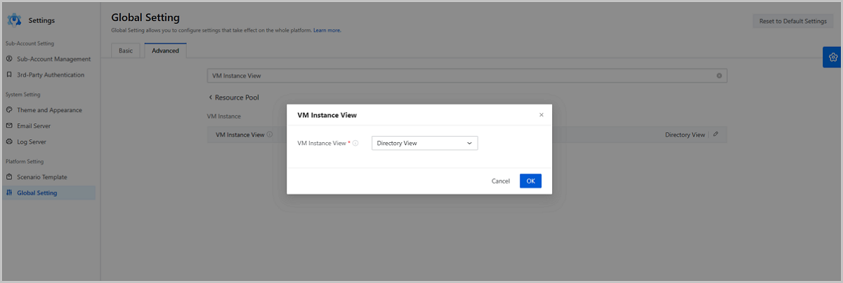
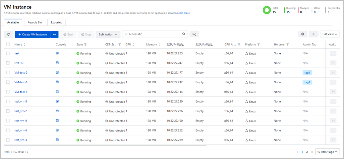
List View | Introduction
Displays VM instance information in a list, such as the VM name, state, CPU, memory, and supported actions.
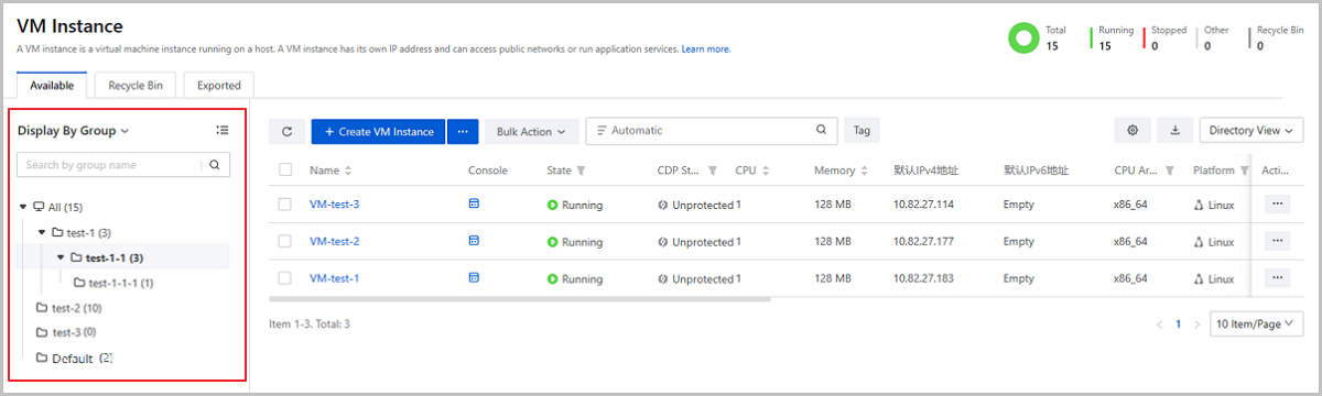
Directory View | Introduction
- Displays VM instance in a directory tree form. You can click the switch
button above the directory tree to make it display VM instances by clusters
where VM instances locate or by groups that VM instances are affiliated to.
 Note:
Note:
- Currently, ECS instances in Hybrid Cloud Management cannot be displayed in directory views.
- Directory views are displayed to admin and platform managers.
and sub-accounts cannot
see a directory view.
图 4. Switch Display Method in Directory View 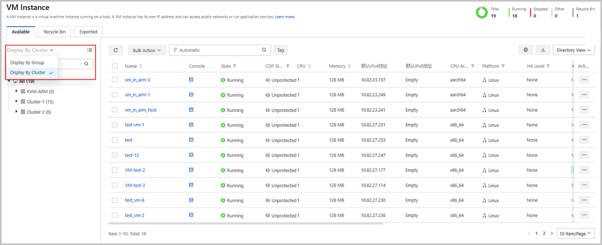
- When you create associated resources based on VM instances, you can filter
needed VM instances by cluster or by group, such as alarms, backup jobs, CDP
tasks, and scheduled jobs.
图 5. Filter VM Instances When Creating Associated Resources 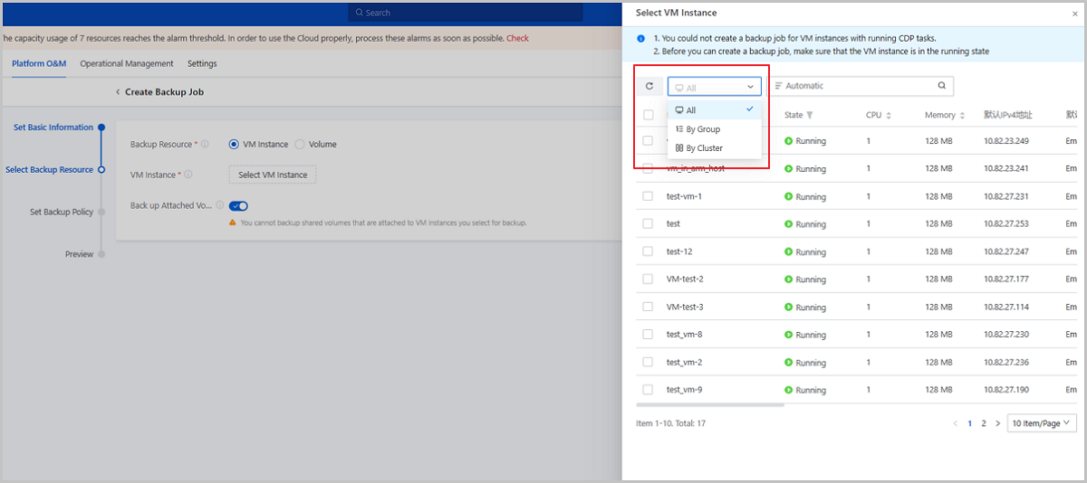
Directory View | Display By Cluster
- Provides a cluster directory tree to display VM instances, helping you view the VM affiliations to clusters and hosts conveniently.
- The cluster directory tree displays all clusters in the current zone and hosts in each cluster. You can specify a cluster to view VM instances in this cluster, or specify a host to view VM instances running on the host.
- You can search a host in the directory tree quickly by the host name.
- You can collapse or expand a whole cluster directory tree.
Directory View | Display By Group
- Provides a group directory tree to display VM instances, helping you view groups that VM instances belong to conveniently.
- The group directory tree displays all VM groups in the current zone and hierarchical relationships between the groups. You can specify a group to view VM instances in this group and its sub-groups.
- You can search a group quickly in the directory tree quickly by the group name.
- You can collapse or expand a whole group directory tree.
Note:
- Groups are separated according to zones where they locate. The directory tree in the current zone does not include groups in other zones.
- A directory tree on the VM Instance page does not include vCenter VM groups.
Directory View | Group Types
- System Group: System groups are automatically provided by the system, including All and Default. All is the root directory in a group directory tree. Default is affiliated to All and is used to manage VM instances that are not allocated to any custom groups.
- Custom Group: Custom groups are created manually as you need. All custom groups are affiliated to the root directory All.
Directory View | Manage Group
| Action | Description |
|---|---|
| Create Group | Create one-level or multiple-level groups.Note:
|
| Create VM Instance | Create VM instances in a specified
group.Note: Only custom groups support this action. You
cannot perform this action on All and
Default. |
| Rename | Modify the name of a group.Note: You can
modify names only for custom groups. You cannot perform this
action on All and Default. |
| Delete Group | Delete a Group.Note:
|
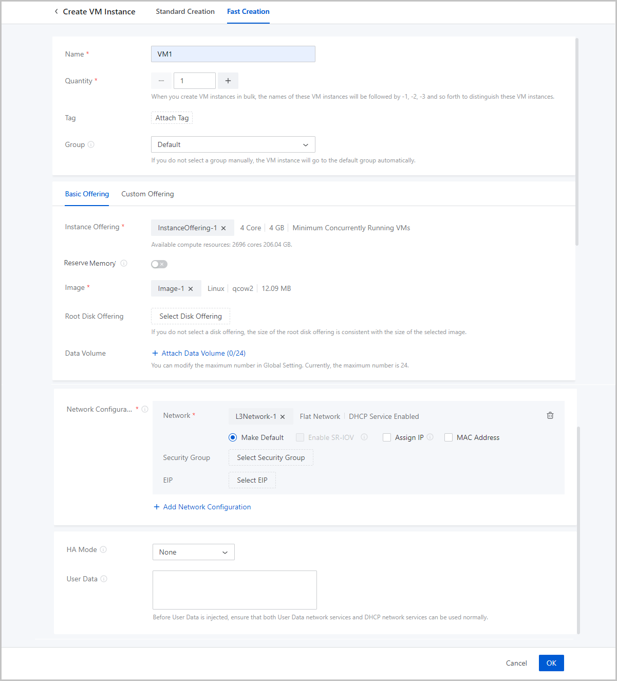
Create a VM Instance (Fast Creation)
- Click the Fast Creation button on the right of Create VM Instance. Then, the Fast Creation page is displayed.
- Click Create VM Instance. On the displayed page, click Fast Creation.
- Name: Enter a name for the VM instance.
The name must be 1 to 128 characters in length and can contain Chinese characters, letters, digits, spaces, hyphens (-), underscores (_), periods (.), parenthesis (), colons (:), and plus signs (+) and cannot begin or end with spaces.
- Quantity: Enter the number of VM instances to be created.
Valid values: 1 to 100. You can change the maximum number by modifying the value
of Maximum VM Creation in Batch on UI in the global
setting.Note: When you create VM instances in bulk, the names of these VM
instances will be followed by -1, -2, -3 and so forth to distinguish these
VM instances.
- Tag: Optional. Bind one or more tags to the VM instance as needed.
- Group: Optional. Choose a VM group for the VM instance.
- Power On: Optional. Choose whether make the VM instance powered on immediately after it is created.
- Set the VM offering by using one of the following methods:Basic Offering: You can set the VM offering by selecting an existing instance offering and disk offering. If you select this method, set the following parameters:
- Instance Offering: Select an existing
instance offering. The instance offering defines the number of CPU
cores, memory size, host allocation strategy, and other
configurations of the VM instance.
- Reserve Memory: The minimum memory that ensures the normal running of the VM instance. By default, this feature is disabled. If you enable this feature, make sure that the reserved memory is less than the memory defined in the instance offering.
- Image: Select an existing image. The image is
used to install an operating system for the VM instance.Note: If you
select an Windows-based ISO image that has enabled Virtio, the
Virtio drive will be attached to the VM operating system by
default. You need to manually install the drive when you install
the operating system. If you reboot the VM instance on the UI,
the drive will be detached.
- Root Disk Offering: Select an existing disk
offering for the root volume of the VM instance. The root disk
offering defines the root volume information such as the size and
disk bandwidth.
- If you select a raw or qcow2 image, this parameter is optional. If you do not select a disk offering, the root disk offering will be consistent with the size of the selected image.
- If you select an ISO image, this parameter is required.
- Data Volume: Optional.
Choose whether to create data volumes and attach the volumes to the
VM instance. You can attach a default maximum of 24 data volumes to
a VM instance. The maximum number can be changed by modifying the
global setting Maximum Data Volume. By default, no data
volumes is created and attached to the VM instance.If you choose to attach a data volume, click Attach Data Volume and set the following parameters:
- Data Disk Offering: Select an existing disk offering for the data volume of the VM instance. The data disk offering defines the data volume information such as the volume size and disk bandwidth.
- Quantity: Enter the number of data volumes created from the selected data disk offering that you want to attach to the VM instance.
- Enable
VirtIOSCSI: Optional. Choose whether to
use a VirtIOSCSI bus to create a SCSI data volume.Note:
- By default, VirtioSCSI is enabled if a shared storage is used, indicating that you can create VirtIO SCSI volumes.
- If a LocalStorage primary storage is used, you can enable VirtioSCSI on the volume details page.
- VirtIOSCSI volumes support multiple I/O queues, which can be identified with IDs (WWN).
Custom Offering: Set the VM offering by customizing the following VM configurations:- CPU: Set the number of CPU cores of the VM instance. Valid values: 1 to 1024, integer.
- Memory: Set the memory size of the VM instance. Valid values: 16 MB to 1000 TB, integer. Unit: MB, GB, and TB.
- Reserve Memory: The minimum memory that ensures the normal running of the VM instance. By default, this feature is disabled. If you enable this feature, make sure that the reserved memory is less than the memory defined in the instance offering.
- Host Allocation Strategy: The strategy used to allocate a host to the VM instance. This strategy is consistent with the global setting Host Allocation Strategy. You can modify this global setting to specify a host allocation policy for the VM instance.
- Image: Select an existing image. This image
is used to install an operating system for the VM instance.Note: If
you select an Windows-based ISO image that has enabled Virtio,
the Virtio drive is attached to the image by default. You need
to manually install the drive when you install the operating
system. If you restart the VM instance on the UI, the drive will
be detached.
- BIOS Mode: Select a BIOS mode for the VM instance. This parameter is required if your image is in the ISO format. By default, the VM BIOS mode is consistent with the image. You can also manually select another one.
- Root Volume: Set
the size of the root volume. Valid values: 1 MB to 1024 TB, integer.
Unit: MB, GB, and TB.
- If you select a raw or qcow2 image, this parameter is optional. If you do not select a disk offering, the size of the root disk offering is consistent with the size of the selected image. If you customize a size, make sure that the size is no smaller than the selected image size.
- If you select an ISO image, this parameter is required. Make sure that the size is no smaller than the selected image size.
- Data Volume: Optional.
Choose whether to create data volumes and attach the volumes to the
VM instance. You can attach a default maximum of 24 data volumes to
a VM instance. The maximum number can be changed by modifying the
global setting Maximum Data Volume. By default, no data
volumes is created and attached to the VM instance.If you choose to attach a data volume, click Attach Data Volume and set the following parameters:
- Data Disk Offering: Select an existing disk offering for the data volume of the VM instance. The data disk offering defines the data volume information such as the volume size and disk bandwidth.
- Quantity: Enter the number of data volumes created from the selected data disk offering that you want to attach to the VM instance.
- Enable
VirtIOSCSI: Optional. Choose whether to
use a VirtIOSCSI bus to create a SCSI data volume.Note:
- By default, VirtioSCSI is enabled if a shared storage is used, indicating that you can create VirtIO SCSI volumes.
- If a LocalStorage primary storage is used, you can enable VirtioSCSI on the volume details page.
- VirtIOSCSI volumes support multiple I/O queues, which can be identified with IDs (WWN).
- Instance Offering: Select an existing
instance offering. The instance offering defines the number of CPU
cores, memory size, host allocation strategy, and other
configurations of the VM instance.
- Network Configurations: Configure the network resources
and network services for the VM instance. You can configure multiple networks
for a VM instance as needed. One network corresponds to a NIC.
- Network: Select an L3 network for the VM
instance. Supported network types: VPC network, public network, and flat network.Note:
- If the L3 network is enabled with the DHCP service, the NIC acquires an IP address in a DHCP mode. The network configurations are deployed by the DHCP service and take effect directly after the VM instance is created.
- If the L3 network is disabled with the DHCP service, the NIC acquires an IP address in a Static mode. You need to install GuestTools for the VM instance after the creation and sync the configurations to the NIC to take effect. If the VM image has encapsulated GuestTools, the network configurations take effect directly after the VM instance is created.
- Make Default: Choose whether to set the network as the default network of the VM instance.
- Enable SR-IOV: Optional. Choose whether to use
SR-IOV to generate a VF NIC and pass it through to the VM instance. By
default, SR-IOV is disabled. You can enable it if you have hardware
resources that satisfy related requirements.Note: To enable SR-IOV, note
that:
- Make sure that SR-IOV network acceleration mode is used for the L2 network from which the L3 network is created. Otherwise, SR-IOV cannot be enabled.
- Enabling SR-IOV generates an NIC of the VF type and passes it through to the VM instance.
- After SR-IOV is enabled, make sure that the physical NIC corresponded by the L3 network has an available VF NIC. Otherwise, the VM instance might fail to be created.
- If you do not enable SR-IOV:
- If the L2 network from which the VM L3 network is created uses Stndard or Smart NIC network acceleration mode, the VM instance is assigned an NIC of the vNIC type.
- If the physical NIC in the L2 network from which the L3 network is created is a Smart NIC, and the L2 network uses Smart NIC network acceleration mode, the VM instance is assigned an NIC of the vDPA type.
- Assign IP: Optional. Choose whether to manually
specify an IP address to the VM NIC.
- If the L3 network is enabled with the DHCP service, the system
can automatically allocate an IP address to the VM NIC according
to the IP allocation policy of the L3 network. You can either
manually specify an IP address or not. If you choose to manually
assign one, set the following parameters:
- Assign IPv4/IPv6: Specify an IP
address on the L3 network for the VM NIC.Note:
- The IP address must be within the network range of the selected network and not be occupied by other resources.
- By default, the drop-down menu displays 5 recommended IP addresses. If the current network has less than 5 IP addresses, all available IP addresses will be displayed.
- If you create VM instances in bulk and specify an IP address here, the Cloud will automatically assign a range of IP addresses to these VM instances with the IP address you specify as the start IP. If an IP address is occupied or if IP addresses are insufficient within the continuously assigned IP range, the corresponding VM instance will fail to be created.
- If the L3 network is disabled with the DHCP service, the
system does not automatically allocate an IP address. To
configure a NIC IP address, you can either assign one on
the Cloud or configure one in the VM instance.If you assign an IPv4 on the Cloud, set the following parameters:
- Assign IPv4: Specify an
IPv4 address for the VM NIC.Note:
- Make sure that the IPv4 address has not been occupied on the Cloud.
- If the L3 network is enabled with IP Address Management, make sure that the IPv4 address is within the network range of the L3 network.
- If you create VM instances in bulk, the IPv4 address you enter is identified as the start IP and assigned to the first VM instance. The IPv4 addresses following it are continuously assigned to the rest VM instances. When an IPv4 has been occupied, the corresponding VM instance fails to be created.
- After the creation, install VM GuestTools and sync NIC configurations to make the IPv4 take effect. If the VM image has encapsulated GuestTools, the IPv4 takes effect directly after the creation.
- Netmask: Set the IPv4 netmask.
- IPv4 Gateway: Optional. Set the IPv4 gateway.
If you assign an IPv6 address on the Cloud, set the following parameters:- Assign IPv6: Specify an
IPv6 address for the VM NIC.Note:
- Make sure that the IPv6 address has not been occupied on the Cloud.
- If the L3 network is enabled with IP Address Management, make sure that the IPv6 address is with in the network range of the L3 network.
- If you create VM instances in bulk, the IPv6 address you enter is identified as the start IP and assigned to the first VM instance. The IPv6 addresses following it are continuously assigned to the rest VM instances. When an IPv4 has been occupied, the corresponding VM instance fails to be created.
- After the creation, install VM GuestTools and sync NIC configurations to make the IPv6 take effect. If the VM image has encapsulated GuestTools, the IPv6 takes effect directly after the creation.
- Prefix Length: Set the IPv6 prefix length.
- IPv6 Gateway: Optional. Set the IPv6 gateway.
If you configure an IP address in the VM instance, the IP address can be read to the Cloud through GuestTools and then managed by the Cloud.Note:
- If the IP address is conflict with IP addresses of other resources on the Cloud, this IP address will not be read and displayed. In addition, an alarm will be triggered.
- If the L3 network is enabled with IP Address Management, make sure that the IP address you configure is within the network of the L3 network.
- The IP address assigned on the Cloud is prior to the IP address configured in the VM instance. If you have assigned an IP address to the NIC on the Cloud, the IP address of the same type you configure in the VM instance will not be displayed on the Cloud be default. For example, if you have assigned an IPv6 to the NIC on the Cloud, the IPv6 you configure for it in the VM instance will not be read and displayed on the Cloud. If you want to make this IP displayed and overwrite that you assign on the Cloud, contact the official technical support to enable the global setting enable.vm.internal.ip.overwrite. This global setting is disabled by default.
- Assign IPv4: Specify an
IPv4 address for the VM NIC.
- Assign IPv4/IPv6: Specify an IP
address on the L3 network for the VM NIC.
- If the L3 network is enabled with the DHCP service, the system
can automatically allocate an IP address to the VM NIC according
to the IP allocation policy of the L3 network. You can either
manually specify an IP address or not. If you choose to manually
assign one, set the following parameters:
- MAC Address: Optional. Choose whether to
customize a MAC address for the VM instance. By default, this option is
not selected and the Cloud automatically assigns a MAC address to the VM
instance.
-
Note:
- If you use the custom configuration, the Cloud assigns a MAC address to the VM instance according to your configurations. In this case, pay attention to avoiding MAC address conflicts.
- If you create VM instances in bulk and choose to assign a MAC address here, the Cloud automatically assigns MAC addresses to these VM instances with the first assigned MAC address as the start address. If a MAC address is occupied within the continuously assigned MAC range, the corresponding VM instance will fail to be created.
-
- Security Group: Optional. Associate an existing security group with the VM instance. If the L3 network is disabled with IP Address Management, assign an IP on the Cloud before you can attach security groups.
- EIP: Optional. Associate an existing elastic IP address (EIP) with the VM instance. If the L3 network is disabled with IP Address Management, you cannot associate an EIP.
- Network: Select an L3 network for the VM
instance. Supported network types: VPC network, public network, and flat network.
- HA Mode: Optional. Specifies whether to enable auto
restart if VM instances are unexpectedly stopped or are errored because of
errors occurred to compute, network, or storage resources associated with the VM
instances. Valid values: None and NeverStop.
- None: The VM instance does not reboot automatically after an unexpected stopping or error.
- Neverstop:
- The VM instance attempts to reboot automatically after it is unexpectedly stopped because of its own errors.
- The VM instance attempts to migrate to another host automatically if errors occur to the compute, network, or storage resource it is residing on.
- The VM instance does not reboot automatically if you stop it
manually, including:
- Manually perform the stopping VM instance, force stopping VM instance, and powering off VM instance actions on the UI.
- Manually run the
shutdown,poweroff, andhaltcommands in the VM OS. - Create a scheduled job to trigger the VM shutdown as planned.
Note:
- By default, a newly created VM uses VM HA Mode Default value in the platform setting. You can modify this value for a VM instance individually during or after the creation. After the modification, the VM instance is not affected by VM HA Mode Default Value in the platform setting.
- If you choose NeverStop, make sure that you have enabled HA Policy in Platform Setting. Otherwise, the NeverStop mode does not take effect.
- User Data: Optional. Inject user-defined parameters or
scripts to customize configurations for the VM instance or to accomplish
specific tasks.Note: To use user data, note that:
- Before you import the user data, make sure that both the user data network service and DHCP network service work as expected.
- Before you inject user data to Linux-based VM instances, make sure that cloud-init is installed on the images of the VM instances. We recommend that you install cloud-init 0.7.9, 17.1, 19.4, 19.4, or later.
- Before you inject user data to Windows-based VM instances, make sure that Cloudbase-Init is installed on the images of the VM instances. You can install Cloudbase-Init of any version. We recommend that you do not modify the default username in Cloudbase-Init. If the Cloudbase-Init default user name is the same as the VM OS username, Cloudbase-Init generates a random password for this OS user and overwrites the password you set.
- If you set the VM password in Login Method, do not set it again in User Data. Otherwise, a conflict may occur.
- If you set the VM hostname both the Hostname input box and User Data. The value in the User Data takes effect.
- Do not set a hostname for a Windows VM instance in UserData during the creation. If you set one, this hostname does not take effect after the creation. To set the hostname for a Windows VM instance, finish the creation and install a GuestTools for the VM instance first.
- If you set a root user password in user data for a VM instance, the password is displayed in the User Data option on the details page of the VM instance. Make sure that your password is well protected.
- You cannot use User Data if the VM instance uses an SR-IOV VF NIC.
Create a VM Instance (Standard Creation)
On the main menu of ZStack Cube Ultimate, choose . Click Create VM Instance. On the displayed page, click Standard Creation.
- Complete the basic configurations.
- Complete the resource configurations.
- Complete the system configurations.
- Confirm the information.
Basic Configurations
- Name: Enter a name for the VM instance.
The name must be 1 to 128 characters in length and can contain Chinese characters, letters, digits, spaces, hyphens (-), underscores (_), periods (.), parenthesis (), colons (:), and plus signs (+) and cannot begin or end with spaces.
- Description: Optional. Enter a description for the VM instance.
- Quantity: Enter the number of VM instances to be
created. You can create VM instances in bulk.Note:
- The quantity must be an integer ranging from 1 to 100.
- You can change the maximum number of the VM instances that you
can create at one time. Method:
Go to , locate Maximum VM Creation in Batch on UI, and change its value as needed. Default: 100.
- Tag: Optional. Bind one or more tags to the VM
instance.Note:
- The Cloud supports 50 tags per resource and an unlimited number of resources per tag.
- Multiple tags can be bound to multiple resources.
- An administrator can unbind or delete tags created by a tenant.
- An administrator can set the number of tags can be created by a
tenant by using the following method:
Go to , locate Tag Default Quota, and change its value as needed. Default: 20.
- Group: Optional. Choose a group for the VM instance.
- Power On: Optional. Choose whether make the VM instance powered on immediately after it is created.
- Set the VM offering by using one of the following methods:
- Basic Offering: Set the VM offering by
selecting an existing instance offering and disk offering.
- Instance Offering: Select an existing
instance offering.
- Reserve Memory: The minimum memory that ensures the normal running of the VM instance. By default, this feature is disabled. If you enable this feature, make sure that the reserved memory is less than the memory defined in the instance offering.
- Image: Select an existing
image.Note: If you select an ISO image encapsulating a
Windows operating system with Virtio enabled. The VM
system will automatically load Virtio drivers. You need
to manually in install the drivers when install the
operating system. After you reboot the VM instance on
UI, the drivers are automatically detached.
- BIOS Mode: Select a BIOS mode for the VM instance. This parameter is required if your image is in the ISO format. By default, the VM BIOS mode is consistent with the image. You can also manually select another one.
- Root Disk Offering: Select an
existing disk offering for the root volume of the VM
instance. The root disk offering defines the root volume
information such as the size and disk bandwidth.
- If you select a raw or qcow2 image, this parameter is optional. If you do not select a disk offering, the size of the root disk offering is consistent with the size of the selected image.
- If you select an ISO image, this parameter is required.
- Data Volume:
Optional. Choose whether to create data volumes and attach
the volumes to the VM instance. You can attach a default
maximum of 24 data volumes to a VM instance. The maximum
number can be changed by modifying the global setting
Maximum Data Volume. By default, no data volumes
is created and attached to a VM instance.If you choose to attach a data volume, click Attach Data Volume and set the following parameters:
- Data Disk Offering: Select an existing disk offering for the data volume of the VM instance. The data disk offering defines the data volume information such as the volume size and disk bandwidth.
- Quantity: Enter the number of data volumes created from the selected data disk offering that you want to attach to the VM instance.
- Enable
VirtIOSCSI: Optional. Choose whether
to use VirtioSCSI bus to create a SCSI data volume.Note:
- By default, VirtioSCSI is enabled if a shared storage is used, indicating that you can create VirtIO SCSI volumes.
- If a LocalStorage primary storage is used, you can enable VirtioSCSI on the volume details page.
- VirtIO SCSI volumes support multiple I/O queues, which can be identified as IDs (WWN).
- Instance Offering: Select an existing
instance offering.
- Custom Offering: Set the VM offering by
customizing the following VM configurations:
- CPU: Set the number of CPU cores of the VM instance. Valid values: 1 to 1024, integer.
- Memory: Set the memory size of the VM instance. Valid values: 16 MB to 1000 TB, integer. Unit: MB, GB, and TB.
- Reserve Memory: The minimum memory that ensures the normal running of the VM instance. By default, this feature is disabled. If you enable this feature, make sure that the reserved memory is less than the memory defined in the instance offering.
- Host Allocation Strategy: The strategy used to allocate a host to a VM instance. This strategy is consistent with the global setting Host Allocation Strategy . You can modify this global setting to specify a host allocation policy for the VM instance.
- Image: Select an existing image.
- Root
Volume: Set the size of the root volume.
Valid values: 1 MB to 1024 TB, integer. Unit: MB, GB, and
TB.
- If you select a raw or qcow2 image, this parameter is optional. If you do not select a disk offering, the size of the root disk offering is consistent with the size of the selected image. If you customize a size, make sure that the size is no smaller than the selected image size.
- If you select an ISO image, this parameter is required. Make sure that the size is no smaller than the selected image size.
- Data Volume:
Optional. Choose whether to create data volumes and attach
the volumes to the VM instance. You can attach a default
maximum of 24 data volumes to a VM instance. The maximum
number can be changed by modifying the global setting
Maximum Data Volume. By default, no data volumes
is created and attached to a VM instance.If you choose to attach a data volume, click Attach Data Volume and set the following parameters:
- Data Disk Offering: Select an existing disk offering for the data volume of the VM instance. The data disk offering defines the data volume information such as the volume size and disk bandwidth.
- Quantity: Enter the number of data volumes created from the selected data disk offering that you want to attach to the VM instance.
- Enable
VirtIOSCSI: Optional. Choose whether
to use VirtioSCSI bus to create a SCSI data volume.Note:
- By default, VirtioSCSI is enabled if a shared storage is used, indicating that you can create VirtIO SCSI volumes.
- If a LocalStorage primary storage is used, you can enable VirtioSCSI on the volume details page.
- VirtIO SCSI volumes support multiple I/O queues, which can be identified as IDs (WWN).
- Basic Offering: Set the VM offering by
selecting an existing instance offering and disk offering.
- Advanced:
- HA Mode: Optional. Specifies whether to
enable auto restart if VM instances are unexpectedly stopped or are
errored because of errors occurred to compute, network, or storage
resources associated with the VM instances. Valid values: None and
NeverStop.
- None: The VM instance does not reboot automatically after an unexpected stopping or error.
- Neverstop:
- The VM instance attempts to reboot automatically after it is unexpectedly stopped because of its own errors.
- The VM instance attempts to migrate to another host automatically if errors occur to the compute, network, or storage resource it is residing on.
- The VM instance does not reboot automatically if you
stop it manually, including:
- Manually perform the stopping VM instance, force stopping VM instance, and powering off VM instance actions on the UI.
- Manually run the
shutdown,poweroff, andhaltcommands in the VM OS. - Create a scheduled job to trigger the VM shutdown as planned.
Note:
- By default, a newly created VM uses VM HA Mode Default value in the platform setting. You can modify this value for a VM instance individually during or after the creation. After the modification, the VM instance is not affected by VM HA Mode Default Value in the platform setting.
- If you choose NeverStop, make sure that you have enabled HA Policy in Platform Setting. Otherwise, the NeverStop mode does not take effect.
- Sync with Host BIOS Time: Optional. Choose
whether to sync Windows VM time with the host BIOS time. If enabled,
Windows VM time is the same as that of the host. By default, the
sync is enabled.Note:
- If you enable time synchronization for a Windows VM instance, the VM time is synchronized with the host BIOS time automatically.
- If you disable time synchronization for a Windows VM instance, the VM time is not synchronized with the host BIOS time.
- If you modify the time synchronization setting for a Windows VM instance, the setting takes effect after the VM instance reboots.
- The time synchronization setting does not take effect on Linux VM instances.
- You can enable time sync in Global Setting for all Windows VM instances on the Cloud. To enable time sync in Global Setting, set Sync with Host BIOS Time to Sync. By default, the time sync global setting is enabled.
- If you specifically set time sync for a Windows VM instance, the global setting does not take effect on the VM instance.
- Resource Priority: Optional. Set a high
resource priority for the VM instance so that VM instance can
compete for more resources in case of resource contention.Note:
- When resource contention occurs due to high host workloads, priority is given to allocating resources to VM instances with the high resource priority.
- We recommend that you set a high resource priority for vital VM instances.
- VM Scheduling Group: Optional. Add the VM
instance to a VM scheduling group.
- A VM instance can be added to only one VM scheduling group. After the addition, the VM instance will be scheduled based on the scheduling policy associated with group.
- The scheduling policies associated with a VM scheduling group can be classified into the following four types: VM Exclusive from Each Other, VM Affinitive to Each Other, VMs Affinitive to Hosts, and VMs Exclusive from Hosts.
- USB Redirection: Optional. Set USB
redirection for the VM instance.Note:
- The Cloud currently supports redirection of multiple USB devices. If you want to use the VDI feature, you can redirect the USB device on the VDI client to the VDI VM instance.
- The setting takes effect after you restart the VM instance.
- Anti-Spoofing Mode: Optional. Enable the
anti-spoofing mode for the VM instance.Note:
- This mode provides IP/MAC anti-spoofing and ARP anti-spoofing for the VM instance. If enabled, the VM instance can only communicate with outside networks by using the IP or MAC addresses allocated by the Cloud.
- You can set whether to enable the anti-spoofing mode
globally by using the following method:
Go to , locate Anti-Spoofing Mode, and enable or disable the switch as needed. Default: false.
- By default, the anti-spoofing mode of a single VM instance is strictly controlled by that in the global setting.
- If anti-spoofing is disabled in the global setting, you can enable it for a single VM instance on the VM details page.
- Anti-spoofing mode is not compatible with IPv6 addresses. We recommend that you do not enable it for the VM instance if you decide to configure an IPv6 address for it because this will make the VM instance fail to communicate through the IPv6 address.
- Instance Offering Online Modification: If
enabled, you can modify the number of vCPUs and memory size of a VM
instance online
- This setting is consistent with the global setting Instance Offering Online Modification by default. However, if you specifically turn on/off this switch for this VM instance, the global setting does not take effect on this VM instance.
- We recommend that you do not modify the number of vCPUs and memory size of a Windows-based VM instance in the production environment.
- XML Hook: Attach an XML Hook to insert or
modify parameters in XML files of the VM instance, thus realizing
custom configurations and specialized functionalities.Note:
- The XML Hook takes effect automatically after the VM instance is created and started.
- If you detach the XML Hook from the VM instance in future, the configurations that are added or modified by the XML Hook will revert to original status.
- HA Mode: Optional. Specifies whether to
enable auto restart if VM instances are unexpectedly stopped or are
errored because of errors occurred to compute, network, or storage
resources associated with the VM instances. Valid values: None and
NeverStop.
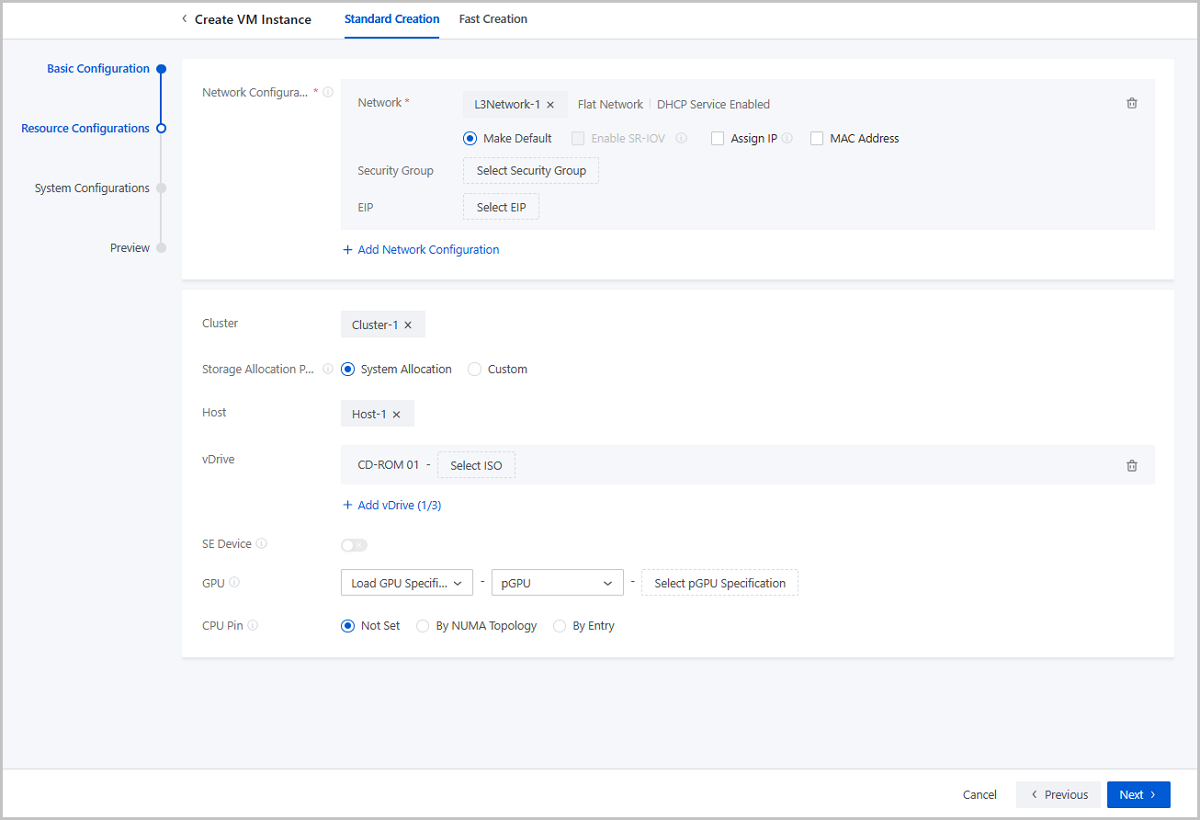
Resource Configurations
- Network Configurations: Configure the network
resources and network services for the VM instance. You can configure
multiple networks as needed. One network corresponds to a NIC.
- Network: Select an L3 network for the VM
instance. Supported network types: VPC network, public network, and
flat network.Note:
- If the L3 network is enabled with the DHCP service, the NIC acquires an IP address in a DHCP mode. The network configurations are deployed by the DHCP service and take effect directly.
- If the L3 network is disabled with the DHCP service, the NIC acquires an IP address in a Static mode. You need to install GuestTools for the VM instance after the creation and sync the configurations to the NIC to take effect. If the VM image has encapsulated GuestTools, the network configurations take effect directly after the VM instance is created.
- Make Default: Choose whether to set the network as the default network of the VM instance.
- Enable SR-IOV: Optional. Choose whether to
use SR-IOV to generate a VF NIC and pass it through to the VM
instance. By default, SR-IOV is disabled. You can enable it if you
have hardware resources that satisfy related requirements.Note: To
enable SR-IOV, note that:
- Make sure that SR-IOV network acceleration mode is used for the L2 network from which the L3 network is created. Otherwise, SR-IOV cannot be enabled.
- Enabling SR-IOV generates an NIC of the VF type and passes it through to the VM instance.
- After SR-IOV is enabled, make sure that the physical NIC corresponded by the L3 network has an available VF NIC. Otherwise, the VM instance might fail to be created.
- If you do not enable SR-IOV:
- If the L2 network from which the VM L3 network is created uses Normal or Smart NIC network acceleration mode, the VM instance is assigned an NIC of the vNIC type.
- If the physical NIC in the L2 network from which the L3 network is created is a Smart NIC, and the L2 network uses Smart NIC network acceleration mode, the VM instance is assigned an NIC of the vDPA type.
- Assign IP: Optional. Choose whether to
manually specify an IP address to the VM NIC.
- If the L3 network is enabled with the DHCP service, the
system can automatically allocate an IP address to the VM
NIC according to the IP allocation policy of the L3 network.
You can either manually specify an IP address or not. If you
choose to manually assign one, set the following
parameters:
- Assign IPv4/IPv6: Specify an
IP address on the L3 network for the VM NIC.Note:
- The IP address must be within the network range of the selected network and not be occupied by other resources.
- By default, the drop-down menu displays 5 recommended IP addresses. If the current network has less than 5 IP addresses, all available IP addresses will be displayed.
- If you create VM instances in bulk and specify an IP address here, the Cloud will automatically assign a range of IP addresses to these VM instances with the IP address you specify as the start IP. If an IP address is occupied or if IP addresses are insufficient within the continuously assigned IP range, the corresponding VM instance will fail to be created.
- If the L3 network is disabled with the DHCP service,
the system does not automatically allocate an IP
address. To configure a NIC IP address, you can
either assign one on the Cloud or configure one in
the VM instance.If you assign an IPv4 on the Cloud, set the following parameters:
- Assign IPv4: Specify an
IPv4 address for the VM NIC.Note:
- Make sure that the IPv4 address has not been occupied on the Cloud.
- If the L3 network is enabled with IP Address Management, make sure that the IPv4 address is within the network range of the L3 network.
- If you create VM instances in bulk, the IPv4 address you enter is identified as the start IP and assigned to the first VM instance. The IPv4 addresses following it are continuously assigned to the rest VM instances. When an IPv4 has been occupied, the corresponding VM instance fails to be created.
- After the creation, install VM GuestTools and sync NIC configurations to make the IPv4 take effect. If the VM image has encapsulated GuestTools, the IPv4 takes effect directly after the creation.
- Netmask: Set the IPv4 netmask.
- IPv4 Gateway: Optional. Set the IPv4 gateway.
If you assign an IPv6 address on the Cloud, set the following parameters:- Assign IPv6: Specify an
IPv6 address for the VM NIC.Note:
- Make sure that the IPv6 address has not been occupied on the Cloud.
- If the L3 network is enabled with IP Address Management, make sure that the IPv6 address is with in the network range of the L3 network.
- If you create VM instances in bulk, the IPv6 address you enter is identified as the start IP and assigned to the first VM instance. The IPv6 addresses following it are continuously assigned to the rest VM instances. When an IPv4 has been occupied, the corresponding VM instance fails to be created.
- After the creation, install VM GuestTools and sync NIC configurations to make the IPv6 take effect. If the VM image has encapsulated GuestTools, the IPv6 takes effect directly after the creation.
- Prefix Length: Set the IPv6 prefix length.
- IPv6 Gateway: Optional. Set the IPv6 gateway.
If you configure an IP address in the VM instance, the IP address can be read to the Cloud through GuestTools and then managed by the Cloud.Note:
- If the IP address is conflict with IP addresses of other resources on the Cloud, this IP address will not be read and displayed. In addition, an alarm will be triggered.
- If the L3 network is enabled with IP Address Management, make sure that the IP address you configure is within the network of the L3 network.
- The IP address assigned on the Cloud is prior to the IP address configured in the VM instance. If you have assigned an IP address to the NIC on the Cloud, the IP address of the same type you configure in the VM instance will not be displayed on the Cloud be default. For example, if you have assigned an IPv6 to the NIC on the Cloud, the IPv6 you configure for it in the VM instance will not be read and displayed on the Cloud. If you want to make this IP displayed can overwrite that one you assign on the Cloud, contact the official technical support to enable the global setting enable.vm.internal.ip.overwrite. This global setting is disabled by default.
- Assign IPv4: Specify an
IPv4 address for the VM NIC.
- Assign IPv4/IPv6: Specify an
IP address on the L3 network for the VM NIC.
- If the L3 network is enabled with the DHCP service, the
system can automatically allocate an IP address to the VM
NIC according to the IP allocation policy of the L3 network.
You can either manually specify an IP address or not. If you
choose to manually assign one, set the following
parameters:
- MAC Address: Optional. Choose whether to
customize a MAC address for the VM instance. By default, this option
is not selected and the Cloud automatically assigns a MAC address to
the VM instance. If you choose to configure a MAC address, set the
following parameters:
- MAC Address: Customize a MAC address for the VM instance.
-
Note:
- If you use the custom configuration, the Cloud assigns a MAC address to the VM instance according to your configurations. In this case, pay attention to avoiding MAC address conflicts.
- If you create VM instances in bulk and choose to assign a MAC address here, the Cloud automatically assigns MAC addresses to these VM instances with the first assigned MAC address as the start address. If a MAC address is occupied within the continuously assigned MAC range, the corresponding VM instance will fail to be created.
- Security Group: Optional. Associate an existing security group with the VM instance. If the L3 network is disabled with IP Address Management, assign an IP on the Cloud before you can attach security groups.
- EIP: Optional. Associate an existing elastic IP address (EIP) with the VM instance. If the L3 network is disabled with IP Address Management, you cannot attach an EIP.
- Network: Select an L3 network for the VM
instance. Supported network types: VPC network, public network, and
flat network.
- Cluster: Optional. Specify a cluster of the host on which the VM instance is to be started.
- Storage Allocation Policy: Specify how the Cloud
allocates a primary storage. Supports two allocation policies: system
allocation and manual allocation.
- System allocation: The Cloud allocates a primary storage according to the preconfigured policy.
- Manual allocation: Select a primary storage manually.
- Host: Optional. Select the host on which the VM instance is to be started. If you specified a cluster, select a host from the cluster.
- vDrive: Optional. Create a virtual drives (vDrive)
for the VM instance.You can click Add vDrives to create more vDrives. Then, you can click Select ISO to attach an ISO to a vDrive.
-
- If you select a qcow2 image or raw image, the Cloud creates an empty vDrive by default. To delete a vDrive, click the deletion icon next to the vDrive parameter.
- If you select an ISO image, the Cloud creates a vDrive by default and attaches the ISO image to the vDrive. Note that this vDrive cannot be deleted here.
- You can set the maximum number of vDrives for a VM instance
after stopping the VM instance. The method is as follows:
Go to , locate Maximum Virtual Drive, and change its value as needed. Default: 3. Valid values: 1, 2, and 3.
-
- GPU: Attach a GPU device to the VM instance by
specifying a GPU specification or device. The GPU device can be either a
physical GPU (pGPU) or a virtual GPU (vGPU).
- Load GPU Specification: Allocate a CPU device according to the selected specification when you create a VM instance.
- Auto Detach GPU Device: Choose whether to
uninstall a GPU device automatically after the VM instance is
stopped.
- If a pGPU specification is used, this option is not selected by default. If a vGPU specification is used, this option is selected by default.
- If selected, the GPU device will be automatically uninstalled after the VM instance is stopped. When the VM instance is restarted, a new GPU device will be allocated to the VM instance according to the GPU specification.
- If not selected, the GPU device will be retained after the VM instance is stopped. When the VM instance is restarted, the existing GPU device will be used.
- Load GPU Device: Attach the GPU device you selected when you create a VM instance.
Note: - You can attach multiple pGPU devices or only one vGPU device to a VM instance at a time.
- You cannot attach both pGPU and vGPU devices to a VM instance at the same time.
- You can attach GPU devices to a VM instance from the host where the VM instance is located. Currently, you cannot attach GPU devices to a VM instance across hosts.
- CPU Pinning: Optional. Assigns the virtual CPUs
(vCPUs) of a VM instance to specific host pCPUs, which improves VM
performance. Three CPU pinning methods are supported: Not Set, By NUMA
Topology, and By Entry.
- Not Set: The vCPUs of the VM instance are not pinned to specific pCPUs but are assigned to pCPUs by the operating system.
- By NUMA Topology: Pins vCPUs to pCPUs based
on the host pNUMA topology. You can implement Manual Pinning or
Smart Pinning.
- Manual Pinning allows you to customize vCPU-pCPU binding for all vCPUs.
- Smart Pinning assigns a vCPU of a VM instance to a pCPU on a host pNUMA node by descending order of the pNUMA node ID. If all pCPUs on the pNUMA node are pinned, a pCPU on the next pNUMA node is to be pinned. If all pCPUs of the host are pinned but some vCPUs are not assigned to pCPUs, each vCPU is assigned to a pCPU starting again from the pNUMA node with the maximum node ID.
- You can pin a vCPU to one or more pCPU or pin one or more vCPU to a pCPU.
- The utilization of each pCPU in the past 15 minutes is displayed. You can pin a vCPU to the optimal pCPU based on the utilization.
- Before you can select By NUMA Topology, you must select a host for the VM instance.
- By Entry:
- You can click Add CPU Pinning to specify more CPU pinning rules.
- Enter the vCPU range in the left text box and the pCPU range
in the right. Note that the - symbol indicates the
value range, while the ^ symbol indicates that a
value is not included. If you specify multiple entries in a
rule, separate each entry by using a comma (,). The
following are some examples:
- 0-2 indicates CPU 0, CPU 1, and CPU 2.
- ^2 indicates that CPU 2 is not included.
- 0-2,^2 indicates CPU 0 and CPU 1.
- 1-7,^2,^3,^4,10 indicates CPU 1, CPU 5, CPU 6, CPU 7, and CPU 10.
Note:
- The vCPU range depends on the selected instance offering of the VM instance, while the pCPU range depends on the selected cluster or the number of pCPUs of the selected host.
- If a vCPU has multiple CPU pinning rules, the union of the rules is used.
- ZStack Cube Ultimate supports CPU overcommitment. Therefore, the number of vCPUs can be greater than that of pCPUs. However, if the number of vCPUs specified in the CPU pinning rule is greater than that of pCPUs, the VM performance will be affected. Therefore, CPU overcommitment is not recommended.
- You can modify the CPU pinning rules on the Overview tab page of a VM details page. The modification takes effect after you restart the VM instance.
- Cloning or migrating a VM instance also copies the CPU pinging rules, while creating a VM image or performing VM backup does not.
- When you create a VM instance, the Cloud firstly checks the VM scheduling policies and host allocation strategies, and then checks the CPU pinning rules.
- When you power off a VM instance and modify its instance offering by reducing the number of the its vCPUs, the CPU pinning rules related to the reduced vCPUs no longer take effect. In this case, we recommend that you modify or delete these rules.
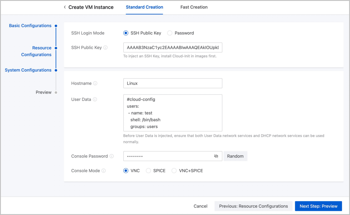
System Configurations
- For Linux VM instances, you can log in to them when they are running by
using an SSH key or a password.
- SSH Key: If you
select this method, set the following parameters:
- SSH Key: Select an SSH key to enable the root user to SSH in to the VM instance without entering a password when the VM instance is running.
Note:
- Make sure that the Cloud-Init is installed in your VM image.
- If your VM image does not have the Cloud-Init installed,
the SSH key attached to the VM instance cannot work
properly. In this scenario, you can try one of the
following methods to make the SSH key work:
- Install the Cloud-Init for the VM instance after the creation and reboot it to make the SSH key work.
- Install the Guesttools (or the QGA of 2.5 or latter version) for the VM instance after the creation. Detach the SSH key from the VM instance first and re-attach it. Then, the SSH key can work properly.
-
Password: If you
select this method, set the following parameters:
- Username: The default username is root.
- Password: After a root password is injected to your VM instance, you can SSH in to the VM instance by entering a password when the VM instance is running.
Note:
- Enter letters, digits, or special characters. Supported special characters include -`=[];',./~!@#$%^&*()_+|{}:"<>?.
- Before you set a password, make sure that Cloud-Init is installed for the VM image.
- If a VM instance runs CentOS, you can install Cloud-Init
by running the
yum install cloud-initcommand. - After you set the password, do not set it again via User Data to avoid conflicts of duplicated operations.
- After you set the password, the password is displayed on User Data of the VM details page. Make sure that your password is well protected.
- You can enable VM Password Strength in Global Setting to set password strength.
- SSH Key: If you
select this method, set the following parameters:
- For Windows VM instances, you can log in to them by using a password only
when they are running.
- Username: The default username is administrator.
- Password: After a password is injected to your VM instance, you can log in to the VM instance by using the password when the VM instance is running.
Note:
- Enter letters, digits, or special characters. Supported special characters include -`=[];',./~!@#$%^&*()_+|{}:"<>?.
- Before you set a login password, make sure that Cloudbase-Init is installed for the VM image. Recommended Cloudbase-Init version: 0.9.11.
- For more information about how to install Cloudbase-Init, see Cloudbase Documentation.
- After you set the password, do not set the it again via User Data to avoid conflicts of duplicated operations.
- After you set the password, the password is displayed on User Data of the VM details page. Make sure that your password is well protected.
- You can enable VM Password Strength in Global Setting to set password strength.
- Hostname: Set a hostname
for the VM instance.Note:
- You cannot set a hostname for a Windows VM instance during the creation. If you need to set, install GuestTools for the VM instance after the creation, and then, click Modify Hostname on the VM action list.
- Linux hostname rules: The hostname must be 2 to 60 characters in length, and can be uppercase, lowercase, digits, and hyphens (-). Note that a hostname cannot contain consecutive hyphens (-) and cannot start or end with hyphens (-).
- To set a hostname, make sure that the DHCP service of the corresponding L3 network is enabled.
- After you set a hostname here, do not set it again in User Data. Otherwise, the password set in the User Data instead of here takes effect.
- User Data: Optional.
Inject user-defined parameters or scripts to customize configurations for
the VM instance or to accomplish specific tasks.
- Before you import user data, make sure that both the user data network service and DHCP network service work as expected.
- By default, the user data network service and DHCP network service in the flat network and VPC network environments are enabled.
- For Linux VM instances:
- Before you inject User Data, make sure that Cloud-Init is installed for the VM image. Recommended Cloud-Init versions: 0.7.9, 17.1, 19.4, 19.4, and later.
- If you set a password in , do not set a password again in User Data. Otherwise, a conflict may occur.
- If you set the VM hostname both the Hostname input box and User Data. The value in the User Data takes effect.
- If you create an Linux VM instance by using an image with Cloud-Init installed, you must import User Data. Otherwise, the Cloud-Init task will wait until timeout.
- For Windows VM instances:
- Before you import User Data, make sure that Cloudbase-Init is installed for the VM image. Recommended Cloudbase-Init version: 0.9.11.
- We recommend that you do not modify the default username in Cloudbase-Init. If the Cloudbase-Init default user name is the same as the VM OS username, Cloudbase-Init generates a random password for this OS user and overwrites the password you set.
- For more information about how to install Cloudbase-Init, see the Cloudbase Documentation.
- If you set the VM password in Login Method, do not set it again in User Data. Otherwise, a conflict may occur.
- Do not set a hostname for a Windows VM instance in UserData during the creation. If you set one, this hostname does not take effect after the creation. To set the hostname for a Windows VM instance, finish the creation and install a GuestTools for the VM instance first.
- If you create a Windows VM instance by using an image with Cloudbase-Init installed, you must import User Data. Otherwise, the Cloudbase-Init task will wait until timeout.
- After you set the login password in User Data, a clear-text password is displayed on User Data of the VM details page. Remember to secure your password.
- When you use User Data, note that: If an L2 network has multiple L3 networks within the same CIDR, only the user data of the first L3 network works. This will make the internal monitoring of the VM instance fail to work properly.
- You cannot use User Data if the VM instance uses an SR-IOV VF NIC.
- The following is an example of importing User Data to a Linux VM
instance.
#cloud-config
users:
 - name: test
   shell: /bin/bash
   groups: users
   sudo: ['ALL=(ALL) NOPASSWD:ALL']
   ssh-authorized-keys:
       - ssh-rsa AAAAB3NzaC1LXCJfjroD1lT root@10-0-0-18
bootcmd:
 - mkdir /tmp/temp
write_files:
 - path: /tmp/ZStack_config
   content: |
       Hello,world!
   permissions: '0755'
fqdn: Perf-test
disable_root: false
ssh_pwauth: yes
chpasswd:
  list: |
      root:word
  expire: False
runcmd:
 - echo ls -l / >/root/list.sh
The preceding script can do the followings:- Create a user named test and use ssh-key when a VM instance is created.
- Write the /etc/hosts file when the VM instance is started, create a directory named /tmp/temp, create a file, and write data to the file.
- Set a hostname, enable the root user, enable SSH login with password, and change the root password.
- Run the
echo ls -l
                                                /
command.
- The following is an example of importing User Data to a Windows VM
instance.
#cloud-config
write_files:
   -   encoding: b64
       content: NDI=
       path: C:\b64
       permissions: '0644'
   -   encoding: base64
       content: NDI=
       path: C:\b64_1
       permissions: '0644'
   -   encoding: gzip
       content: !!binary |
           H4sIAGUfoFQC/zMxAgCIsCQyAgAAAA==
       path: C:\gzip
       permissions: '0644'
The preceding script can do the following:- Create b64, b64_1, and gzip files under C drive when the VM instance is started.
- Console Password: Set a
console password for the VM instance. The password must be 6 to 8 characters
long.
- Enter letters, digits, and special characters. Supported special characters include -`=[];',./~!@#$%^&*()_+|{}:"<>?.
- If you select the VNC mode, you can enable VNC Console Password Strength in Global Setting to set password strength.
- If you set a console password, you need to enter the password when you launch the console.
- Console Mode: Set the
console mode. Options: VNC, SPICE, and VNC+SPICE. Default: VNC.Note:
- If not set, the console mode specified in the global setting will be used by default.
- If you set this parameter here, the VM instance will use the mode you select.
- If you change the console mode of a VM instance, reboot the VM instance to take effect.
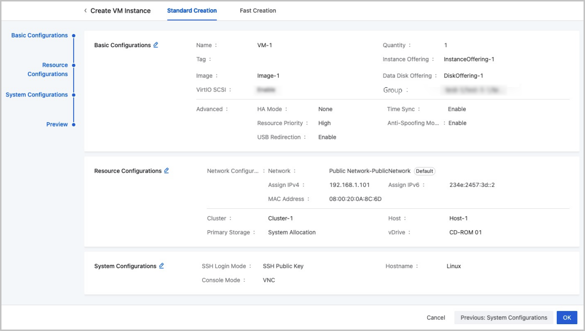
Confirm Information
View the information about the VM instance to be created. You can edit the information by clicking the Edit icon.
Considerations
-
- Image BIOS modes include Legacy and UEFI. A VM instance inherits the BIOS mode from its image.
- You need to get the corresponding image ready, and select a proper BIOS mode for it.
- You can change the BIOS mode on the VM details page. Exercise with caution when you make any changes. The VM instance may fail to work properly because of an incompatible BIOS mode. After you change the BIOS mode, restart the VM instance to make the change take effect.
- The Legacy mode is recommended when you create a VM instance. If you
want to use the UEFI mode, we recommend that you select the
corresponding image from the following list of operating system
versions.
OS BIOS Mode Supported Versions Windows UEFI - Windows 8 or later
UEFI - Windows 7
- Windows Server 2008 R2
Linux UEFI - CentOS 7.2
- CentOS 7.3
- CentOS 7.4 or later
Note: SSH methods vary according to image types.- Operating System
- Linux Image: Fixed user name: root. SSH method: with the SSH public key or password.
- Windows Image: Fixed user name administrator. You can use a User Data to modify the password.
- Image Format
- ISO: SSH with the SSH public key.
- Image: SSH with the SSH public key or password.
Import a VM Instance (Via Third-Party Template)
On the main menu of ZStack Cube Ultimate, choose . Select Import from the Create VM Instance drop-down list and you are redirected to the Import page.
- Select an OVF template file.Set the following parameters:
- Image Storage: Select an ImageStore or Ceph image storage to temporarily store the template file. After the VM instance is created, the file will be auto-deleted.
- Template Type: Only OVF template is supported.
- OVF File: The OVF-formatted file in the uploaded OVF template. You can select only one file at a time.
- VMDK File: The VMDK-formatted files in the uploaded OVF template. The number of files and the file configurations must be consistent with that defined in the OVF-formatted file.
- MF File: The MF-formatted file in the uploaded OVF template. You can select only one file at a time.
图 1. Upload OVF Template File 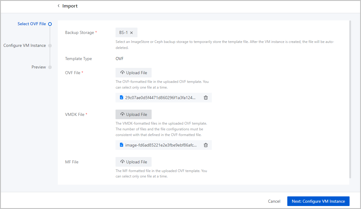
- Configure the VM instance.Set the following parameters:
- Name: Enter a name for the VM instance.
The name must be 1 to 128 characters in length and can contain Chinese characters, letters, digits, spaces, hyphens (-), underscores (_), periods (.), parenthesis (), colons (:), and plus signs (+) and cannot begin or end with spaces.
- Description: Optional. Enter a description for the VM instance.
- Tag: Optional. Bind one or more tags to the
VM instance.Note:
- The Cloud supports 50 tags per resource and an unlimited number of resources per tag.
- Multiple tags can be bound to multiple resources.
- An administrator can unbind or delete tags created by a tenant.
- An administrator can set the number of tags a tenant can
create by using the following method:
Go to , locate Tag Default Quota, and change its value as needed. Default: 20.
- Instance Offering of Template: The instance offering of the imported VM instance is displayed.
- Cluster: Optional. Specify a cluster of the
host on which the VM instance is to be started.
- Hosts that apply the KVM virtualization technology can be added only to KVM-based clusters.
- You can enable network acceleration for a KVM-based cluster.
If you add a host to a cluster for which network
acceleration is enabled, note that:
- If the L2 network associated with the cluster uses the Smart NIC network acceleration mode, the host must be attached with a smart NIC of the specified model.
- Hosts of the X-Dragon architecture can be added only to X-Dragon-based clusters.
- Network Configurations: Select an L3 network
used by the VM instance and complete the network configurations.
- Network: Select an L3 network used by
the VM instance. Supported network types: public network,
flat network, and VPC network.Note:
- If the L3 network is enabled with the DHCP service, the NIC acquires an IP address in a DHCP mode. The network configurations are deployed by the DHCP service and take effect directly.
- If the L3 network is disabled with the DHCP service, the NIC acquires an IP address in a Static mode. You need to install GuestTools for the VM instance after the creation and sync the configurations to the NIC to take effect. If the VM image has encapsulated GuestTools, the network configurations take effect directly after the VM instance is created.
- Make Default: If you add multiple network configurations, set one of the networks as the default network.
- Enable SR-IOV:
Optional. Choose whether to use SR-IOV to generate a VF NIC
and pass it through to the VM instance.
- By default, SR-IOV is not enabled. In this case, the VM instance you create will have a vNIC attached.
- If enabled, the VM instance you create will have a VF NIC attached.
Note: To enable SR-IOV, note that:- Only IPv4 networks support SR-IOV, but IPv6 or IPv4+IPv6 networks do not.
- Make sure that SR-IOV is enabled for the L2 network corresponding to the L3 network of the VM instance. Otherwise, SR-IOV cannot be enabled.
- After SR-IOV is enabled, make sure that the physical NIC corresponded by the L3 network has an available VF NIC. Otherwise, the VM instance might fail to be created.
- If SR-IOV is enabled, NICs of the VM instances created by using a public network or a flat network do not support the network services such as security group and EIP. If the VM instances is created by using a VPC network, their NICs do not support the security group network services.
- Assign IP: Optional. Choose whether to
manually specify an IP address to the VM NIC.
- If the L3 network is enabled with the DHCP service,
the system can automatically allocate an IP address
to the VM NIC according to the IP allocation policy
of the L3 network. You can either manually specify
an IP address or not. If you choose to manually
assign one, set the following parameters:
- Assign IPv4/IPv6:
Specify an IP address on the L3 network for the VM NIC.Note:
- The IP address must be within the network range of the selected network and not be occupied by other resources.
- By default, the drop-down menu displays 5 recommended IP addresses. If the current network has less than 5 IP addresses, all available IP addresses will be displayed.
- If you create VM instances in bulk and specify an IP address here, the Cloud will automatically assign a range of IP addresses to these VM instances with the IP address you specify as the start IP. If an IP address is occupied or if IP addresses are insufficient within the continuously assigned IP range, the corresponding VM instance will fail to be created.
- If the L3 network is disabled with the DHCP
service, the system does not automatically
allocate an IP address. To configure a NIC IP
address, you can either assign one on the Cloud or
configure one in the VM instance.If you assign an IPv4 on the Cloud, set the following parameters:
- Assign IPv4: Specify an
IPv4 address for the VM NIC.Note:
- Make sure that the IPv4 address has not been occupied on the Cloud.
- If the L3 network is enabled with IP Address Management, make sure that the IPv4 address is within the network range of the L3 network.
- If you create VM instances in bulk, the IPv4 address you enter is identified as the start IP and assigned to the first VM instance. The IPv4 addresses following it are continuously assigned to the rest VM instances. When an IPv4 has been occupied, the corresponding VM instance fails to be created.
- After the creation, install VM GuestTools and sync NIC configurations to make the IPv4 take effect. If the VM image has encapsulated GuestTools, the IPv4 takes effect directly after the creation.
- Netmask: Set the IPv4 netmask.
- IPv4 Gateway: Optional. Set the IPv4 gateway.
If you assign an IPv6 address on the Cloud, set the following parameters:- Assign IPv6: Specify an
IPv6 address for the VM NIC.Note:
- Make sure that the IPv6 address has not been occupied on the Cloud.
- If the L3 network is enabled with IP Address Management, make sure that the IPv6 address is with in the network range of the L3 network.
- If you create VM instances in bulk, the IPv6 address you enter is identified as the start IP and assigned to the first VM instance. The IPv6 addresses following it are continuously assigned to the rest VM instances. When an IPv4 has been occupied, the corresponding VM instance fails to be created.
- After the creation, install VM GuestTools and sync NIC configurations to make the IPv6 take effect. If the VM image has encapsulated GuestTools, the IPv6 takes effect directly after the creation.
- Prefix Length: Set the IPv6 prefix length.
- IPv6 Gateway: Optional. Set the IPv6 gateway.
If you configure an IP address in the VM instance, the IP address can be read to the Cloud through GuestTools and then managed by the Cloud.Note:
- If the IP address is conflict with IP addresses of other resources on the Cloud, this IP address will not be read and displayed. In addition, an alarm will be triggered.
- If the L3 network is enabled with IP Address Management, make sure that the IP address you configure is within the network of the L3 network.
- The IP address assigned on the Cloud is prior to the IP address configured in the VM instance. If you have assigned an IP address to the NIC on the Cloud, the IP address of the same type you configure in the VM instance will not be displayed on the Cloud be default. For example, if you have assigned an IPv6 to the NIC on the Cloud, the IPv6 you configure for it in the VM instance will not be read and displayed on the Cloud. If you want to make this IP displayed can overwrite that one you assign on the Cloud, contact the official technical support to enable the global setting .enable.vm.internal.ip.overwrite. This global setting is disabled by default.
- Assign IPv4: Specify an
IPv4 address for the VM NIC.
- Assign IPv4/IPv6:
Specify an IP address on the L3 network for the VM NIC.
- If the L3 network is enabled with the DHCP service,
the system can automatically allocate an IP address
to the VM NIC according to the IP allocation policy
of the L3 network. You can either manually specify
an IP address or not. If you choose to manually
assign one, set the following parameters:
- MAC Address: Optional. Choose whether
to configure a MAC address for the VM instance.
- By default, this option is not selected and the Cloud automatically assigns a MAC address to the VM instance.
- If you choose to configure a MAC address, set the
following parameters:
- MAC Address: Customize a MAC address for the VM instance.
-
Note:
- If you use the custom configuration, the Cloud assigns a MAC address to the VM instance according to your configurations. In this case, pay attention to avoid MAC address conflicts.
- If you create VM instances in bulk and choose to assign a MAC address here, the Cloud automatically assigns MAC addresses to these VM instances with the MAC address you specify as the start address. If a MAC address is occupied within the continuously assigned MAC range, the corresponding VM instance will fail to be created.
- Security Group: Optional. Associate a
security group with the VM instance.
The security group is used to better protect the VM instance by implementing access control in the group. You can customize access rules in the security group. These rules take effect immediately when the VM instance joins the security group. This protects the VM instance in real time.
- EIP: Optional. Associate an elastic
IP address (EIP) with the VM instance.Note: This parameter
does not appear if you selected a public
network.
- Network: Select an L3 network used by
the VM instance. Supported network types: public network,
flat network, and VPC network.
- Startup Now: Choose whether to startup the VM instance immediately after the import is completed. By default, the imported VM instance is not started up immediately
- Advanced:
- Storage Allocation Policy:
- If you select System Allocation, the Cloud
allocates a primary storage according to the
preconfigured policy.
- Host: Optional. Select the host on which the VM instance is to be started.
- If you select Manual
Allocation, you can select a primary
storage as needed.
- Primary Storage: Select a primary storage for the VM instance.
-
- Host: Optional. Select the host on which the VM instance is to be started.
- If you select System Allocation, the Cloud
allocates a primary storage according to the
preconfigured policy.
- HA Mode: Optional. Specifies whether
to enable auto restart if VM instances are unexpectedly
stopped or are errored because of errors occurred to
compute, network, or storage resources associated with the
VM instances. Valid values: None and NeverStop.
- None: The VM instance does not reboot automatically after an unexpected stopping or error.
- Neverstop:
- The VM instance attempts to reboot automatically after it is unexpectedly stopped because of its own errors.
- The VM instance attempts to migrate to another host automatically if errors occur to the compute, network, or storage resource it is residing on.
- The VM instance does not reboot automatically if it is stopped manually or through a scheduled job.
Note:
- By default, a newly created VM uses VM HA Mode Default value in the platform setting. You can modify this value for a VM instance individually during or after the creation. After the modification, the VM instance is not affected by VM HA Mode Default Value in the platform setting.
- If you choose NeverStop, make sure that you have enabled HA Policy in Platform Setting. Otherwise, the NeverStop mode does not take effect.
- Resource Priority: Optional. Set a
high resource priority for the VM instance so that it can
compete for more resources in case of resource contention.Note:
- When resource contention occurs due to high host workloads, priority is given to allocating resources to VM instances with the high resource priority.
- We recommend that you set a high resource priority for vital VM instances.
- Storage Allocation Policy:
图 2. Configure VM Instance 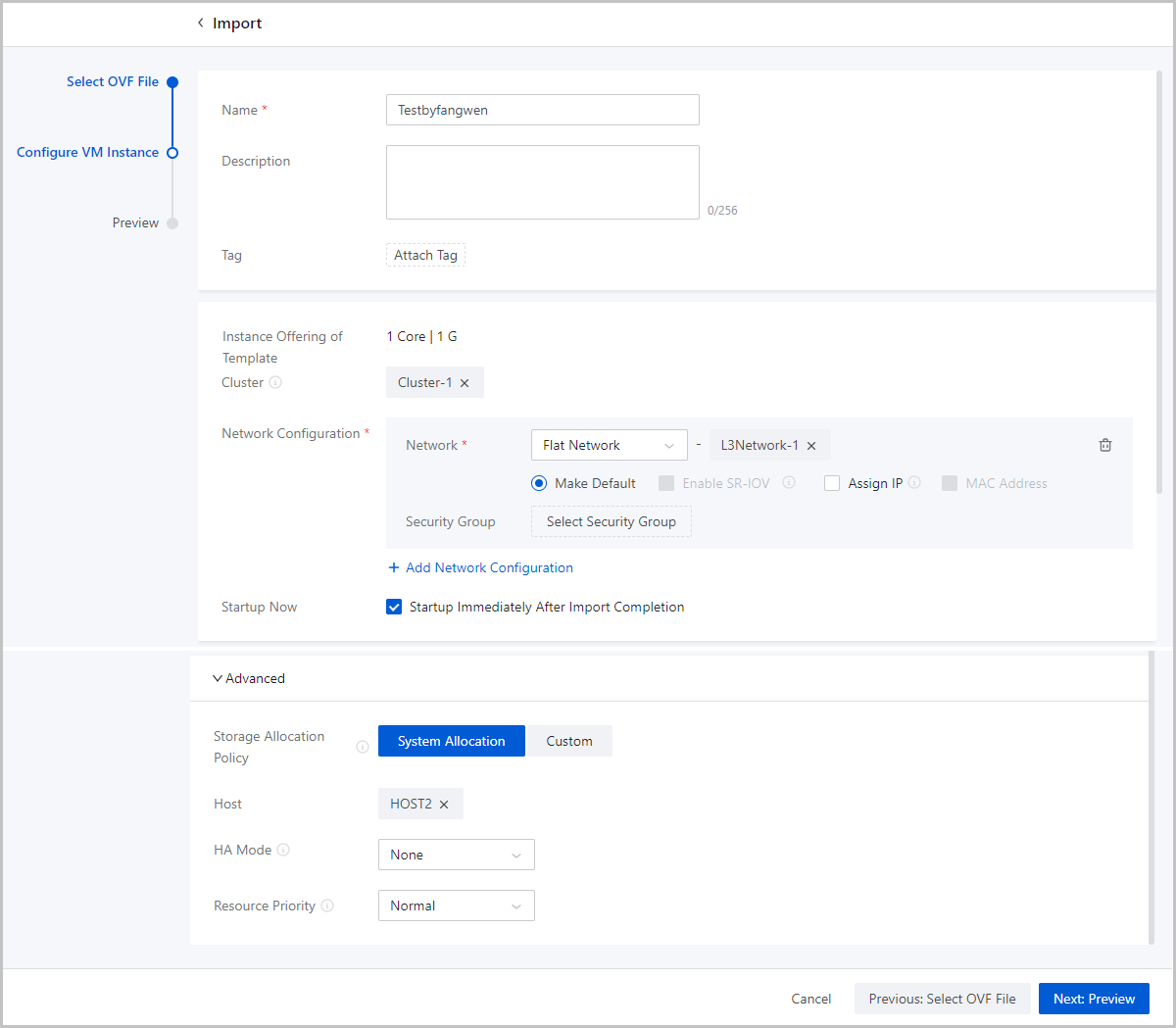
- Name: Enter a name for the VM instance.
- Confirm the information.
View the information about the VM instance. You can edit the information by clicking the Edit icon.
图 3. Confirm Information 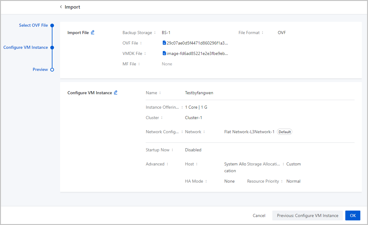
Considerations
- The root volume of the imported VM instance is of the IDE type and the data volumes of the VM instance is of the Virtio type. If the data volumes do not have the Virtio drive attached before the import, you need to install GuestTools on the imported VM instance and then start up the VM instance. Then the data volumes can be identified.
- Imported VM instances go to the default group.
Manage a VM Instance
On the main menu of ZStack Cube Ultimate, choose . Then, the VM Instance page is displayed.
| Action | Description | VM State |
|---|---|---|
| Create VM Instance | Create one or more VM instances. The Cloud
provides two creation methods: standard creation and fast creation.Note:
|
/ |
| Import VM Instance | Import VM instances on a third-party cloud
platform with an OVF template and customize the VM
configurations.Note: Imported VM instances go to the default
group. |
/ |
| Edit VM Instance | Edit the name and description of a VM instance. | Running/Stopped/Paused |
| Change Group | Change the VM group a VM instance affiliated to. | Running/Stopped/Paused |
| Start VM Instance | Start a stopped VM instance. | Stopped |
| Stop VM Instance | Stop a running VM instance.Note: If the VM
instance has HA enabled, note that the VM instance does not HA
restart after you manually stop it. |
Running |
| Reboot VM Instance | Reboot a running VM instance. | Running |
| Restore VM Instance | Restore a paused VM instance. | Paused |
| Pause VM Instance | Pause a running VM instance.Note: Pausing a VM
instance does not really stop the VM instance. However, stopping
the host on which the paused VM instance is located will affect
the business running. |
Running |
| Force Stop VM Instance | Forcibly change the VM state from Unknown to Stopped.Note:
|
Unknown |
| Power Off VM Instance | Power off a running VM instance.Note:
|
Running |
| Launch Console | Launch the console of a VM instance. ZStack Cube Ultimate includes command line scripting for
managing hosts and VM instances.Note:
|
Running |
| Clone VM Instance | Clone a VM instance that has the same system as
the current VM instance based on the VM instance offering.
Note:
Note:
|
Running/Stopped/Paused |
| Modify Hostname | Modify the hostname of the VM instance.
Note: The VM hostname must comply with the following rules:
|
Running/Stopped/Paused |
| Flatten VM Instance | Merges multiple snapshots of selected resources
to improve resource performance and data security. By flattening,
you can unlink the dependency between linked clone VM
instances/volumes and source VM instances/volumes to achieve data independence.Note:
|
Running/Stopped/Paused |
| Attach Tag to VM Instance | Attach tags to a VM instance so that you can
locate and query it quickly.
Note:
|
Running/Stopped/Paused |
| Detach Tag from VM Instance | Detach tags from the VM instance.Note:
|
Running/Stopped/Paused |
| Change Host | Hot or cold migrate a VM instance to another
host. This action changes only the host where the VM instance runs
and does not change its primary storage. ZStack Cube Ultimate supports operating system clustering
with shared-disk failover capability from one VM to another VM that
is running on another host.
|
Running/Stopped |
| Change Primary Storage | Hot or cold migrate a VM instance to another
primary storage. This action changes only the primary storage used
by the VM instance and does not change the host. Changing primary
storage only migrates valid data, and the migrated VM instance
follows the provisioning type of the target primary storage.
Currently, migration across SharedBlock primary storages and across
SharedBlock and Ceph primary storages are supported.
|
Running/Stopped |
| Change Host and Primary Storage | Cold or hot migrate a VM instance to another host
and primary storage. After you change the primary storage, the host
where the VM instance resides is changed based on the system policy
or your manual allocation choice. When cold migrate a VM instance,
only system allocation is supported for target host.
Note: Before you migrate a VM instance, detach the ISOs, block
devices, and peripheral devices (if any) from the VM instance
first.
|
Running/Stopped |
| Modify Instance Offering | Modify the instance offering of a VM
instance.Note: After the modification,
only the CPU, memory, and host allocation policy in the new
instance offering take effect for the VM instance.
|
Running/Stopped |
| Set GPU Policy | Set the GPU policy for a VM instance. Supported
policies: Attach GPU Device and Attach GPU Specification.
|
Stopped |
| Resize Root Volume | Expand the root volume size of a VM instance.
|
Running/Stopped |
| Change Owner | Change the owner of a VM instance.Note: Changing a VM owner detaches all of the
tenant tags on this VM instance. Admin tags are not
affected. |
Running/Stopped |
| Change System | Change the system of a VM instance.
Note:
|
Stopped |
| Reimage VM Instance | Restore a VM instance to the initial state of the
VM image and overwrite all the data in the root volume.
Note: Please back up the original root volume data in advance
to avoid data loss. |
Stopped |
| Set Boot Order | Set a boot order for a VM instance.
|
Running/Stopped |
| Boot from Host | Specify a host on which a VM instance boots.
Note: If a VM instance is associated with a VM scheduling
policy, it is scheduled primarily based on the policy. You
cannot specify a host for the VM instance to run. |
Stopped |
| Set VM HA | Set the high availability (HA) mode for a VM
instance.
|
Running/Stopped |
| Sync with Host BIOS Time | Set Windows VM time to sync with the host BIOS
time. If enabled, Windows VM time is the same as that of the host.
By default, the sync is enabled.Note:
|
Running/Stopped/Paused |
| Sync with Host System Time | Set VM time to sync with the host system time. If
enabled, the VM time is the same as that of the host system. By
default, the sync is disabled.Note:
|
|
| Set Error Policy | Set the error policy for a VM instance, including
error inspection and error handling.
|
Running |
| Attach SSH Key | Attach an SSH public key to a VM instance. Then,
you can SSH into the VM instance with the corresponding private key. Note:
|
Running |
| Detach SSH Key | Detach the SSH key from the VM
instance.Note: Make sure that the VM instance satisfies the
following requirements:
|
Running |
| Change VM Password | Change the username/password of a VM instance.
Note:
|
Running |
| Set VM Console Password | Set a console password or cancel the console
password for a VM instance.
|
Running/Stopped |
| Toggle Console Mode | Toggle the console mode for a VM instance. The
console mode includes VNC, SPICE, and VNC+SPICE.
|
Running/Stopped/Paused |
| Set RDP Mode | Set the RDP mode for the VDI UI. Then, the VM console is opened in the RDP mode. | Running/Stopped/Paused |
| Resource Priority | Set the resource priority for a VM instance.
Note:
|
Running/Stopped/Paused |
| Cluster Binding | Choose whether to make the VM instance bound to
the cluster it is residing on.
|
Running/Stopped/Paused |
| Kernel Same-Page Merging | Specifies whether enable Kernel Same-Page Merging
for the VM instance. If you enable Kernel Same-Page Merging, the system detects whether this VM instance and other VM instances use virtual memory pages mapped to physical memory pages with identical content and re-maps these virtual memory pages to the same physical memory page, thus reducing duplicated occupation of physical memory resources. Note:
|
Running/Stopped/Paused |
| Memory Balloon | Specifies whether enable Memory Balloon for the
VM instance. If you enable Memory Balloon, the system monitors in real time the memory usage of VM instances and the host. If the workloads running on the VM instance decrease, the host reclaims unused memory of the VM instance when the physical memory usage is higher than 80%. If the workloads running on the VM instance increase, the host allocates necessary memory space to the VM instance. This dynamic reclaim and allocation mechanism makes sure the efficient use of host memory. Note:
|
Running/Stopped/Paused |
| Upload File | Upload files to the specified path of a VM instance.Note:
|
Running |
| Execute Command | Execute a command on the VM instance.Note:
|
Running |
| Execute Script | Execute a script on a VM instance. Note:
|
Running |
| Attach XML Hook | Attach an XML Hook to a VM instance. The XML Hook
can modify the VM XML file to realize custom configurations or
extended functionalities.Note:
|
Running/Stopped |
| Detach XML Hook | Detach a XML Hook from a VM instance.Note:
|
Running/Stopped/Deleted |
| USB Redirection | Set USB redirection for a VM instance.
|
Running/Stopped/Paused |
| Create Snapshot | Create a snapshot for a VM instance.
Note:
|
Running/Stopped/Paused |
| Create Backup | Create a backup for a VM instance.
|
Running |
| Associate Backup Job | Associate a backup job with a VM instance.
|
Running/Paused |
| Attach Volume | Attach an available data volume to a VM
instance.Note:
|
Running/Stopped |
| Detach Volume | Detach a volume from a VM instance.Note:
|
Running/Stopped |
| Create Image | Create a template image based on a custom VM
instance so that you can use it to create VM instances with same
configurations in bulk.
|
Running/Stopped |
| Attach ISO | Attach an ISO to a VM instance.
Note: If the number of virtual drives attached by a VM instance
has exceeded the setting in the Global Setting, the Global
Setting does take effect for this VM instance. |
Running/Stopped |
| Detach ISO | Detach an ISO from a VM instance.Note: Detaching
an ISO from a running VM instance might affect the business
continuity. Please exercise caution. |
Running/Stopped |
| Add to VM Scheduling Group | Add a VM instance to a VM scheduling group. After the addition, the scheduling policies associated with the group take effect on the VM instance immediately. | Running/Stopped |
| Remove from VM Scheduling Group | Remove a VM instance from a VM scheduling group. After the removal, the VM instance will no longer be scheduled based on scheduling policies associated with the group. | Running/Stopped |
| Export VM Instance | Export a VM instance to an image storage. After
the VM instance is exported, you can view and download the exported
file on the Exported tab of this VM instance.Note:
|
Stopped |
| Delete VM Instance | Deleting a VM instance releases the associated
CPU, memory, and IP address. The deleted VM instance is put into
Recycle Bin.
Note: You can delete a VM instance with all attached volumes
except for shared volumes. |
|
| Expunge/Recover VM Instance | You can completely delete or recover a VM
instance in the recycle bin.
|
Deleted |
| Copy URL | Copy the URL of an exported VM instance. | Running/Stopped/Paused |
| Download exported VM Instance | Download an exported VM Instance to your local PC. | Running/Stopped/Paused |
| Delete Export Record | Delete the export record of a VM instance. | Running/Stopped/Paused |
VM Details
VM Console
On ZStack Cube Ultimate, you can enter a VM instance by launching the VM console with one click from the VM action list. In the VM console, you can perform various actions on the VM operating system, such as installing the operating system, log in to the operating system, executing commands, or running programs.
This topic introduces how to configure, access, and use a VM console in details.
Access VM Console
- Console Mode: You can select a remote desktop access protocol for
ZStack Cube Ultimate to connect to the VM console.
Supports three mode: VNC, SPICE, and VNC+SPICE.
- By default, the console mode of a newly created VM instance is consistent with the value of the global setting Console Mode.
- You can modify the console mode for a VM instance individually during or after the creation. Then, the global setting does not take effect on this VM instance.
- If you modify the console mode for a VM instance, restart the VM instance to make the new mode take effect.
- Console Password: You can set a console password for a VM instance
during or after the creation to ensure the remote access security.
- By default, the console password must be 6~8 characters in length and can contain letters, digits, and the following special characters: -`=[];',./~!@#$%^&*()_+|{}:"<>?
- You can adjust the password requirement through the global setting VNC Console Password Strength Policy.
- If you set a console password for a VM instance, you must use the correct password to enter the VM console. If you do not set a console password or cancel the password, you can enter the VM console directly by clicking Launch Console.
- If you set or cancel the console password, restart the VM instance to make the setting take effect.
- Console Proxy: You can set or view the console proxy information by clicking on the main menu of ZStack Cube Ultimate. ZStack Cube Ultimate connects to VM consoles through the proxy address you configure here. Only when the proxy state is Enabled can you launch VM consoles successfully. By default, the console proxy address is the management node IP address.
Quick Functions on Console Page
- Local Command Paster: The first button on the left side of the console page. Click this button, and the Paste command page appears. You can paste commands here and click OK to paste commands to the console to be executed conveniently.
- Tools: The second button on the left side of the console page, which is a collection of several hotkeys, including Ctrl, Alt, Win, Tab, Esc, and Ctrl+Alt+Del.
- Power Management: The third button on the left side of the console page, which allows you to stop, reboot, resume, pause, or power off a VM instance on the console page directly. Starting the VM instance is not supported on the console page.
- Setting: The forth button on the left side of the console page, which allows you to enable/disable a Read Only mode for the console. If you enable the Read Only mode, you cannot enter commands or perform other actions in the VM console.
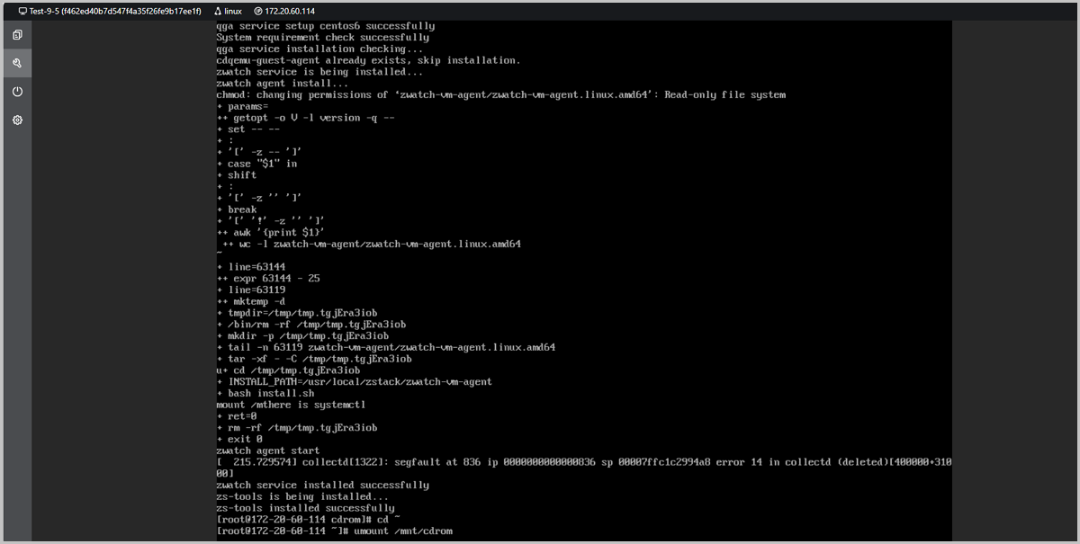
VM GuestTools
VM instance GuestTools is a collection of drivers and tools that help improve VM performance and enable more VM functions. This topic describes the composition, installation, and application of VM GuestTools.
Composition
- Linux: The GuestTools for Linux VM instances consists of internal
monitoring agent and QGA.
- Internal monitoring agent: An agent responsible for obtaining VM internal monitoring data, including CPU, memory, and disk capacity data.
- QEMU Guest Agent (QGA):A program used for interactions between VM
instances and enabling features like configuration deployment,
configuration reading, and automated O&M.Note: Linux operating
systems typically come with built-in VirtIO drivers and
Cloud-Init, so the GuestTools for Linux VM instances does not
include these two components separately. If your Linux operating
system does not include VirtIO and Cloud-Init, you can install
them through other methods.
Different Linux operating systems vary on the compatibility with the GuestTools. The following lists the compatibility details of each component in GuestTools.- Yes: You can install this component by installing GuestTools and use features relying on this component properly.
- No: You cannot install this component by installing GuestTools or cannot use features relying on this component properly after the installation.
OS Version Internal Monitoring Agent QGA CentOS CentOS 6.5 64 bit No Yes CentOS 6.6 64 bit Yes Yes CentOS 6.7 64 bit Yes Yes CentOS 6.8 64 bit Yes Yes CentOS 6.9 64 bit Yes Yes CentOS 6.10 64 bit Yes No CentOS 7.2 64 bit Yes Yes CentOS 7.3 64 bit Yes Yes CentOS 7.4 64 bit Yes Yes CentOS 7.5 64 bit Yes Yes CentOS 7.6 64 bit Yes Yes CentOS 7.9 64 bit Yes Yes CentOS 8.0 64 bit Yes Yes CentOS 8.1 64 bit Yes Yes CentOS 8.2 64 bit Yes Yes CentOS 8.3 64 bit Yes Yes CentOS 8.4 64 bit Yes Yes CentOS 8.5 64 bit Yes Yes CentOS Stream 8 64 bit Yes Yes CentOS Stream 9 64 bit Yes Yes CentOS Stream 10 64 bit Yes Yes RHEL Redhat Enterprise Linux Server 6.9 64 bit Yes No Redhat Enterprise Linux Server 7.0 64 bit Yes No Redhat Enterprise Linux Server 7.1 64 bit Yes No Redhat Enterprise Linux Server 7.2 64 bit Yes No Redhat Enterprise Linux Server 7.3 64 bit Yes No Redhat Enterprise Linux Server 7.4 64 bit Yes Yes Redhat Enterprise Linux Server 7.5 64 bit Yes Yes Redhat Enterprise Linux Server 7.6 64 bit Yes Yes Redhat Enterprise Linux Server 7.7 64 bit Yes Yes Redhat Enterprise Linux Server 7.8 64 bit Yes Yes Redhat Enterprise Linux Server 7.9 64 bit Yes Yes Redhat Enterprise Linux Server 8.0 64 bit Yes Yes Redhat Enterprise Linux Server 8.1 64 bit Yes Yes Redhat Enterprise Linux Server 8.2 64 bit Yes Yes Redhat Enterprise Linux Server 8.3 64 bit Yes Yes Redhat Enterprise Linux Server 8.4 64 bit Yes Yes Redhat Enterprise Linux Server 8.5 64 bit Yes Yes Redhat Enterprise Linux Server 8.6 64 bit Yes Yes Redhat Enterprise Linux Server 8.8 64 bit Yes Yes Redhat Enterprise Linux Server 8.9 64 bit Yes Yes Redhat Enterprise Linux Server 8.10 64 bit Yes Yes Redhat Enterprise Linux Server 9.0 64 bit Yes Yes Redhat Enterprise Linux Server 9.2 64 bit Yes Yes Redhat Enterprise Linux Server 9.4 64 bit Yes Yes Redhat Enterprise Linux Server 10 64 bit Yes Yes Fedora Fedora 30 64 bit Yes Yes Fedora 31 64 bit Yes Yes Fedora 42 64 bit Yes Yes Debian Debian 9.9 64 bit Yes Yes Debian 10.13 64 bit Yes Yes Debian 11.9 64 bit Yes Yes Debian 12.5 64 bit Yes Yes Debian 13 64 bit Yes Yes Ubuntu Ubuntu 14.04 64 bit Yes Yes Ubuntu 16.04 64 bit Yes Yes Ubuntu 16.10 64 bit Yes Yes Ubuntu 18.04 64 bit Yes Yes Ubuntu 20.04 64 bit Yes Yes Ubuntu 22.04 64 bit Yes Yes Ubuntu 24.04 64 bit Yes Yes Kylin Kylin V4.0.2 64 bit Yes No Kylin V10 SP1(0518) 64 bit Yes Yes Kylin V10 SP2 64 bit Yes Yes Kylin V10 SP3 64 bit Yes Yes Kylin V11 64 bit Yes Yes NeoKylin NeoKylin V7.0 64 bit Yes Yes NeoKylin V7update6 64 bit Yes Yes OpenSUSE OpenSUSE Leap 15.0 64 bit Yes Yes SLES SUSE Linux Enterprise Server 11 64 bit Yes Yes SUSE Linux Enterprise Server 12 64 bit Yes Yes SUSE Linux Enterprise Server 15 64 bit Yes Yes SUSE Linux Enterprise Desktop 12 64 bit Yes Yes SUSE Linux Enterprise Desktop 15 64 bit Yes Yes UOS UOS V20 1050e Yes Yes Oracle Linux Oracle Linux 7.9 Yes Yes Oracle Linux 8 Yes Yes Oracle Linux 9 Yes Yes OpenEuler OpenEuler 20 64 bit Yes Yes OpenEuler 22 64 bit Yes Yes OpenEuler 24.03 Yes Yes Rocky Rocky 8.8 64 bit Yes Yes Rocky 8.9 64 bit Yes Yes Rocky 9.4 64 bit Yes Yes Rocky 10 64 bit Yes Yes Alma Linux Alma Linux 9.3 64 bit Yes Yes Alma Linux 9.4 64 bit Yes Yes Anolis AnolisOS 8.6 64 bit Yes Yes AnolisOS 8.8 64 bit Yes Yes AWS Amazon Linux 2023 Yes Yes - Windows: The GuestTools for Windows VM instances consists of internal
monitoring agent, QGA, VirtIO driver, and Cloudbase-Init.
- VirtIO driver: A collection of drivers to improve the VM
performance.
- SCSI controller: used to improve the disk performance of a Windows VM instance in a virtualization environment.
- PCI simple communications controller: used to realize the communications between a Windows VM instance and the underlying KVM virtualization.
- PCI device: used to realize the balloon memory scaling.
- Ethernet adapter: used to improve the network performance of a Windows VM instance in a virtualization environment.
- Cloudbase-Init: A component helps realize the User Data import and other customized functions.
Different Windows operating systems vary on the compatibility with the GuestTools. The following lists the compatibility details of each component in GuestTools.- Yes: You can install this component by installing GuestTools and use features relying on this component properly.
- No: You cannot install this component by installing GuestTools or cannot use features relying on this component properly after the installation.
OS Version Internal Monitoring Agent QGA VirtIO Driver Cloudbase-Init Windows Windows Server 2008 R2 64 bit Yes Yes Yes No Windows Server 2012 64 bit Yes Yes Yes Yes Windows Server 2016 64 bit Yes Yes Yes Yes Windows Server 2019 64 bit Yes Yes Yes Yes Windows Server 2022 64 bit Yes Yes Yes Yes Windows Server 2025 64 bit Yes Yes Yes Yes - VirtIO driver: A collection of drivers to improve the VM
performance.
- FreeBSD: The GuestTools for FreeBSD VM instances consists of internal
monitoring agent.
OS Version Internal Monitoring Agent FreeBSD FreeBSD 11 64 bit Yes FreeBSD 12 64 bit Yes FreeBSD 13 64 bit Yes
Installation
- Linux VM Instances
- Click Install GuestTools on the VM details page.
- Attach an ISO of VM GuestTools.
- Run the following installation commands on the VM instance console:
# Create a mount point.
mkdir /mnt/cdrom
# Mount the CND-ROM image.
mount /dev/cdrom /mnt/cdrom
#
cd /mnt/cdrom/
bash ./zs-tools-install.sh
# Unmount the CD-ROM image.(Optional)
cd ~
umount /mnt/cdrom
Note:
- You can copy the commands by one click from the VM details page to the VM instance console.
- Before you install GuestTools, make sure that you have installed the appropriate Linux command tools, such as tar, wget, and curl.
- For VM instance of OpenEuler OS, you need to disable
selinuxafter installing GuestTools, otherwise it will affect the QGA function.
图 1. Install GuestTools for Linux VM Instance 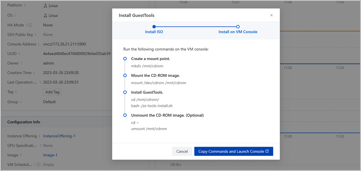
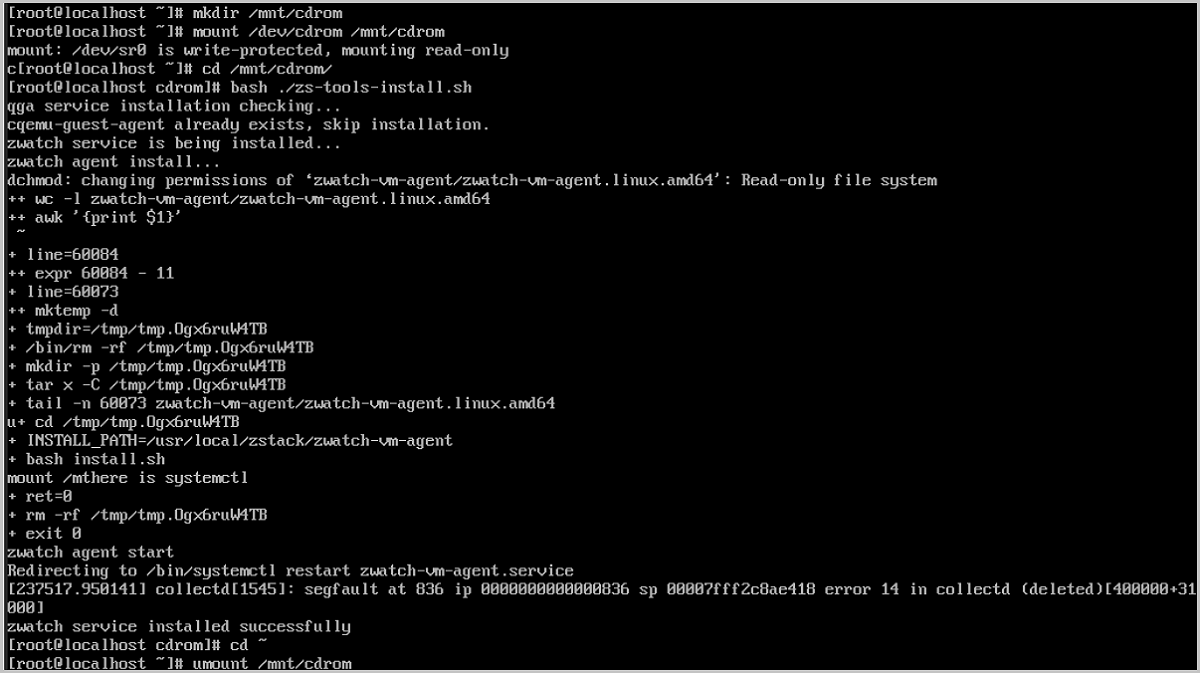
- Windows VM Instance
- Click Install GuestTools on the VM details page.
- Attach an ISO of VM GuestTools.
- Launch the VM console and install GuestTools as prompted.
图 2. Install GuestTools for 
- FreeBSD VM Instance
- Click Install GuestTools on the VM details page.
- Run the following installation commands on the VM instance console:
curl http://169.254.169.254/vm-tools.sh -o vm-tools.sh && bash -x ./vm-tools.shNote:
- In the command above, 169.254.169.254 is the IP address of the User Data server.
- Before you install GuestTools, make sure that you installed the bash, security/libgcrypt, and curl tools.
图 3. Install GuestTools for FreeBSD VM Instance 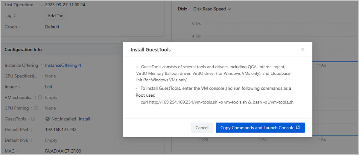
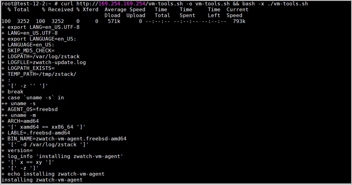
Application
| Action | Description |
|---|---|
| Internal Monitoring | Obtains monitoring data from the VM instance and displays monitoring dynamically in graphs. For more information, see Internal Monitoring. |
| Configuration Deployment |
|
| Configuration Reading | Reads the NIC IP address you configure in the
VM instance to the Cloud through the QGA in the GuestTools. An
IP address configured in the VM instance can be displayed on and
managed by the Cloud after it is read successfully.
|
| Automated O&M | Perform actions like executing scripts, executing commands, and uploading files on a VM instance to finish automated O&M jobs. For more information, see descriptions of Execute Script, Execute Command, and Upload File in Manage a VM Instance. |
| Memory Balloon & Kernel Same-Page Merging | Allows you to enable Memory Balloon and Kernel Same-Page Merging for a VM instance to improve the use efficiency of host memory. For detailed information, see descriptions of Memory Balloon and Kernel Same-Page Merging in Advanced Settings |
VM CPU Mode
The VM CPU mode specifies whether to select the same CPU model as the host for a VM instance.
| VM CPU Architecture | VM CPU Mode | VM CPU Model for Cluster | Description | Note |
|---|---|---|---|---|
| x86_64 | Inherit Cluster Setting (by default)
|
none (by default) | The CPU model of VM instances in the cluster is simulated via QEMU. In this mode, the VM instances inherit necessary host CPU features to a small degree. You can select this mode if you need to migrate your VM instances. |
|
| host-model | The CPU model of VM instances in the cluster is similar to or same as that of the host, such as Haswell Intel CPU. In this mode, VM instances inherit many host CPU features. You can select this mode if you need to migrate VM instances. | |||
| host-passthrough | The CPU model and CPU features of VM instances in the cluster are all the same as the CPU model and CPU features of hosts in the cluster. For example, both VM instances and hosts support the extended page table extension, huge page, and virtualization features. Compared with the none, host-model, and Custom modes, VM instances in this mode have the most CPU features. You can select this mode if your business requires many features. | |||
| Custom (a specified CPU model) | VM instances in the cluster share the specified CPU model. Different CPU models may have different CPU features. Note that if your host CPU is Hygon and the OS of your VM instance is an earlier version such as Windows Server 2012 R2 and Windows Server 2008 R2, you can select Hygon_Customized. | |||
| none | N/A | The CPU model of VM instance is simulated via QEMU. In this mode, the VM instance inherits necessary host CPU features to a small degree. We recommend you select this mode if you need to migrate your VM instance. | ||
| host-model | N/A | The CPU model of the VM instance is similar to or same as that of the host, such as Intel Haswell CPU. In this mode, the VM instance inherits many host CPU features. You can select this mode if you need to migrate your VM instance. | ||
| host-passthrough | N/A | The CPU model as well as CPU features of the VM instance are the same as the CPU model and CPU features of the host. For example, both the VM instance and host support the extended page table extension, huge page, and virtualization features. Compared with the none, host-model, and Custom modes, VM instance in this mode has the most CPU features. You can select this mode if your business requires many features. | ||
| Custom (a specified CPU model) | N/A | The CPU model of the VM instance is set to the specified model. Different CPU models may have different CPU features. Note that if your host CPU is Hygon and the OS of your VM instance is an earlier version such as Windows Server 2012 R2 or Windows Server 2008 R2, you can select Hygon_Customized. | ||
| aarch64 | Inherit Cluster Setting (by default)
|
none (by default) | The CPU model of VM instances in the cluster is simulated via QEMU. In this mode, the VM instances inherit necessary host CPU features to a small degree. You can select this mode if you need to migrate your VM instances. | |
| host-model | The CPU model of VM instances in the cluster is the same as that of the host. In this mode, VM instances inherit many host CPU features. You can select this mode if you need to migrate VM instances. | |||
| host-passthrough | The CPU model as well as CPU features of VM instances in the cluster are all the same as the CPU model and CPU features of hosts in the cluster. Compared with the host-model and Custom modes, VM instances in this mode have most CPU features. You can select this mode if your business requires many features. | |||
| Custom (a specified CPU model) | VM instances in the cluster share the specified CPU model. Different CPU models may have different CPU features. | |||
| host-model | N/A | The CPU model of the VM instance is similar to or same as that of the host. In this mode, the VM instance inherits many host CPU features. You can select this mode if you need to migrate your VM instance. | ||
| host-passthrough | N/A | The CPU model as well as CPU features of the VM instance are the same as the CPU model and CPU features of the host. VM instance in this mode has the most CPU features. You can select this mode if your business requires many features. | ||
| Custom (a specified CPU model) | N/A | The CPU model of the VM instance is set to the specified model. Different CPU models may have different CPU features. | ||
| mips64el | A specified CPU model | N/A | The CPU model of the VM instance is set to the specified model. | |
| loongarch64 | A specified CPU model | N/A | The CPU model of the VM instance is set to the specified model. |
VM Configurations
On the main menu of ZStack Cube Ultimate, choose . On the VM Instance page, click on the name of a VM instance. Then, the details page of the VM instance is displayed. Click on the Configuration Info tab page. Then, the Configuration Info tab page is displayed.
The Configuration Info tab page displays the configuration information about the VM instance in the form of a list.
Volume
| Action | Description | VM State |
|---|---|---|
| Set Root Volume | Set a data volume attached by the VM instance
as a root volume.Note:
|
Stopped |
| Attach to Current VM Instance | Attach a detached data volume to the VM instance again. | Running/Stopped |
NIC
| Action | Description | VM State |
|---|---|---|
| Enable NIC | Enable a disabled NIC. All NIC configurations
are kept same before and after the enablement.Note: You can only
enable NICs of the vNIC type. |
Running/Paused/Stopped |
| Disable NIC | Disable an NIC. After the disablement, the
Cloud will keep all NIC configurations.Note:
|
Running/Paused/Stopped |
| Attach NIC | Attach an NIC to the VM instance.
Note:
|
Running/Stopped |
| Detach NIC | Detach a NIC from the VM instance.Note:
|
Running/Stopped |
| Set NIC Type | Change the NIC type from a VF NIC to a vNIC.Note:
|
Stopped |
| Set MAC | Set a MAC address the VM NIC.Note:
|
Stopped |
| Set the NIC Model | Set the NIC model for the VM instance.
supported VM NIC models: virtio, rtl8139, and e1000.Note:
|
Stopped |
| Set NIC QoS | Set the upstream bandwidth and downstream
bandwidth of the VM NIC.
|
Running/Stopped |
| Set Network and IP Address | Modify the network or IP address used by the
VM NIC.
|
Running/Stopped |
| Set Security Group | Attach/Detach security groups to/from the VM
NIC. And set a default policy for flows that are not stipulated
by the security groups.Note:
|
Running/Stopped |
| Set Default Network | Set a default network for the VM instance if
the VM instance has multiple NICs.Note: Reboot the VM instance
to take effect. |
Running/Stopped |
| Attach EIP | Attach an EIP to the VM NIC.Note:
|
Running/Stopped |
| Detach EIP | Detach an EIP from the VM NIC. | Running/Stopped |
| Synchronize Configurations | Deploys and updates NIC configurations
according to the parameters you set on the Cloud, including IP
address, netmask, gateway, DNS, and MTU.Note:
|
Running |
vDrive
| Action | Description | VM State |
|---|---|---|
| Create vDrive | Create a vDrive for the VM instance.Note:
|
Stopped |
| Set as Default Drive | Set a vDrive for the VM instance if the VM instance has
multiple vDrives.Note:
|
Stopped |
| Delete vDrive | Delete a vDrive.Note:
|
Stopped |
LUN
| Action | Description | VM State |
|---|---|---|
| Attach LUN | Pass through a LUN provided by an iSCSI or FC storage to the
VM instance directly as a storage medium.Note:
|
Running/Stopped |
| Detach LUN | Detach a LUN from the VM instance.Note: This operation
interrupts the data reads/writes and may affect the business
continuity. Please exercise caution. |
Running/Stopped |
pGPU Device
| Action | Description | VM State |
|---|---|---|
| Attach pGPU Device | Pass through a pGPU device to a VM instance directly.Note:
|
Running/StoppedNote: If you use Hygon GPUs, you can attach
them only when the VM is stopped. |
| Detach pGPU Device | Detach a pGPU device from the VM instance.Note:
|
Running/StoppedNote: If you use Hygon GPUs, you can detach
them only when the VM is stopped. |
vGPU Device
| Action | Description | VM State |
|---|---|---|
| Attach vGPU Device | Pass through a vGPU device to a VM instance directly.Note:
|
Stopped |
| Detach vGPU Device | Detach a vGPU device from the VM instance.Note: Before you
detach a vGPU device from a VM instance, stop the VM
instance first. |
Stopped |
USB Device
| Action | Description | VM State |
|---|---|---|
| Attach USB Device | Pass through a USB device to a VM instance directly. The
following two attach modes are supported:
Note: To attach a USB device to a VM instance, note the
following:
|
Running/Stopped |
| Detach USB Device | Detach a USB device from the VM instance.Note: This operation
interrupts the data reads/writes on the USB device. Please
exercise caution. |
Running/Stopped |
Other Device
| Action | Description | VM State |
|---|---|---|
| Attach Other Device | Pass through a PCI device to the VM instance.Note: To attach
a PCI device to a VM instance, note the following:
|
Running/Stopped |
| Detach Other Device | Detach a PCI device from the VM instance.Note: This operation
might affect the business continuity. Please exercise
caution. |
Running/Stopped |
Advanced Settings
ZStack Cube Ultimate allows you to set the advanced parameters of a VM instance. This setting takes effect only for the VM instance. If not set, the values set in the Global Setting will be used by default.
| Parameter | Description |
|---|---|
| Instance Offering Online Modification |
|
| Hyper-V Virtualization | Specifies whether to enable Hyper-V of a VM instance. By default, Hyper-V is disabled. Note that you can set Hyper-V for Windows-based VM instances only. |
| NIC Queue Number | Set the number of queues when VirtIO NIC traffics are allocated to multiple CPUs. By default, the number of queues is consistent with the number of vCPUs of the VM instance and is 12 at maximum. For example, if the number of vCPUs of the VM instance and is 16, the default value is 12. Valid values: 1 to 256, integer. |
| VM Instance Hypervisor | Specifies whether to enable the hypervisor tag for the VM CPU. Default: true. If set to false, the VM CPU hypervisor tag is disabled, which is used to skip virtualization environment detections from applications on the VM instance. |
| Memory Balloon | Monitors in real time the memory usage of VM
instances and the host. If the workloads running on a VM instance
decrease, the host reclaims unused memory of the VM instance when
the host memory usage is higher than 80%. If the workloads running
on a VM instance increase, the host allocates necessary memory space
to the VM instance. This dynamic reclaim and allocation mechanism
makes sure the efficient use of host memory. Default: false. Note:
|
| Kernel Same-Page Merging | Detects whether this VM instance and other VM
instances use virtual memory pages mapped to physical memory pages
with identical content and re-maps these virtual memory pages to the
same physical memory page, thus reducing duplicated occupation of
physical memory resources. Default: true.Note:
|
| Vendor ID | If a VM instance is running on a host with a
Hygon CPU, we recommend that you set its Vendor ID as
AuthenticAMD to ensure the compatibility of various VM OS
and make the VM instance run properly. If you set it to None,
some VM OS may fail to be compatible with the Hygon CPU, which may
cause VM errors.Note: This setting applies to VM instances running
on hosts with Hygon CPU only. |
External Monitoring
The External Monitoring tab displays the VM performance data, such as the CPU utilization, memory usage, disk speed, disk IOPS, NIC data transfer rate, NIC packet rate, and NIC packet discard rate, obtained from a host by using libvirt. These data is displayed dynamically in real time through graphs. However, if the VM instance uses an SR-IOV VF NIC, you cannot view external monitoring statistics.
CPU Utilization
- Available time spans: 15 minutes, 1 hour, 6 hours, 1 day, 1 week, 1 month, 1 year, and custom.
- Monitoring metrics:
- Select All: Displays the utilization of all CPUs and the average CPU utilization. The average utilization and utilization of different CPUs are displayed in different colors.
- Average: Displays the average of all CPUs of a VM instance.
- Specified CPU: Displays the utilization of a specified CPU. You can specify one or more CPU. The utilization of different CPUs are displayed in different colors.
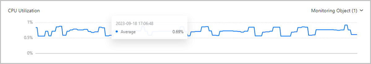
Memory Usage
- Available time spans: 15 minutes, 1 hour, 6 hours, 1 day, 1 week, 1 month, 1 year, and custom.
- Monitoring metrics:
- Select All: Displays the used memory and free memory. The used memory and free memory are displayed in different colors.
- Used: Display the used memory of the VM instance.
- Free: Display the free memory of the VM instance.
 Note:
Note:
virsh dommemstat command provided by
libvirt.# Obtain the ID of the VM instance.
[root@localhost ~]# virsh list
Id Name State
----------------------------------------------------
1 fe3790c408204c9998ccd6b54272fab1 running
# Obtain the real-time memory utilization of the VM instance. Unit: KB.
[root@localhost ~]# virsh dommemstat 1
actual 2097152
swap_in 0
swap_out 16
major_fault 698
minor_fault 686260
unused 23876
available 2048544
rss 2147224Memory Reclaim
- Available time spans: 15 minutes, 1 hour, 6 hours, 1 day, 1 week, 1 month, 1 year, and custom.
- Memory reclaim mechanism: Monitors in real time the memory usage of VM
instances and the host. Its dynamic reclaim and allocation mechanism makes
sure the efficient use of host memory:
- If the workloads running on a VM instance decrease, the host reclaims unused memory of the VM instance.
- If the workloads running on a VM instance increase, the host allocates necessary memory space to the VM instance.
- Memory reclaim is triggered only after the host memory usage exceeds 80%.

Disk Speed
- Available time spans: 15 minutes, 1 hour, 6 hours, 1 day, 1 week, 1 month, 1 year, and custom.
- Monitoring metrics:
- Select All: Displays the read and write speed of a disk. The read and write speed are displayed in different colors.
- Read: Displays the read speed of a disk.
- Write: Displays the write speed of a disk.
- Monitoring object:
- Select All: Display the read/write speed of all disk partitions. Read/write speed of different disk partitions are displayed in different colors.
- Specified Disk Partition: Display the read/write speed of a specified disk partition. You can specify one or more disk partition. Read/write speed of different disk partitions are displayed in different colors.
Disk IOPS
- Available time spans: 15 minutes, 1 hour, 6 hours, 1 day, 1 week, 1 month, 1 year, and custom.
- Monitoring metrics:
- Select All: Displays the read and write IOPS of a disk. The read and write IOPS are displayed in different colors.
- Read: Displays the read IOPS of a disk.
- Write: Displays the write IOPS of a disk.
- Monitoring object:
- Select All: Display the read/write IOPS of all disk partitions. Read/write IOPS of different disk partitions are displayed in different colors.
- Specified Disk Partition: Display the read/write IOPS of a specified disk partition. You can specify one or more disk partition. Read/write IOPS of different disk partitions are displayed in different colors.
NIC Data Transfer Rate
- Available time spans: 15 minutes, 1 hour, 6 hours, 1 day, 1 week, 1 month, 1 year, and custom.
- Monitoring metrics:
- Select All: Displays the transfer speed of data out/in a VM NIC. The out/in rate are displayed in different colors.
- Out: Displays the transfer speed of data out of a VM NIC.
- In: Displays the transfer speed of data accessing a VM NIC.
- Monitoring objects:
- Select All: Displays the data transfer rate of all VM NICs. Rate of different NICs are displayed in different colors.
- Specify NIC: Displays the data transfer rate of specified VM NICs. You can specify one or more NIC. Rate of different NICs are displayed in different colors.
NIC Packet Rate
- Available time spans: 15 minutes, 1 hour, 6 hours, 1 day, 1 week, 1 month, 1 year, and custom.
- Monitoring metrics:
- Select All: Displays the speed of data packet out/in a VM NIC. The out/in rate are displayed in different colors.
- Out: Displays the transfer speed of data packets out of a VM NIC.
- In: Displays the transfer speed of data packets accessing a VM NIC.
- Monitoring objects:
- Select All: Displays the packet rate of all VM NICs. Rate of different NICs are displayed in different colors.
- Specify NIC: Displays the packet rate of specified VM NICs. You can specify one or more NIC. Rate of different NICs are displayed in different colors.
NIC Packet Discard Rate
- Available time spans: 15 minutes, 1 hour, 6 hours, 1 day, 1 week, 1 month, 1 year, and custom.
- Monitoring metrics:
- Select All: Displays the discard rate of packets out/in a VM NIC. The discard rates of out/in packets are displayed in different colors.
- Out: Displays the discard rate of packets out of a VM NIC.
- In: Displays the discard rate of packets accessing a VM NIC.
- Monitoring objects:
- Select All: Displays the packet discard rate of all VM NICs. Discard rate of different NICs are displayed in different colors.
- Specify NIC: Displays the packet rate of specified VM NICs. You can specify one or more NIC. Discard rate of different NICs are displayed in different colors.
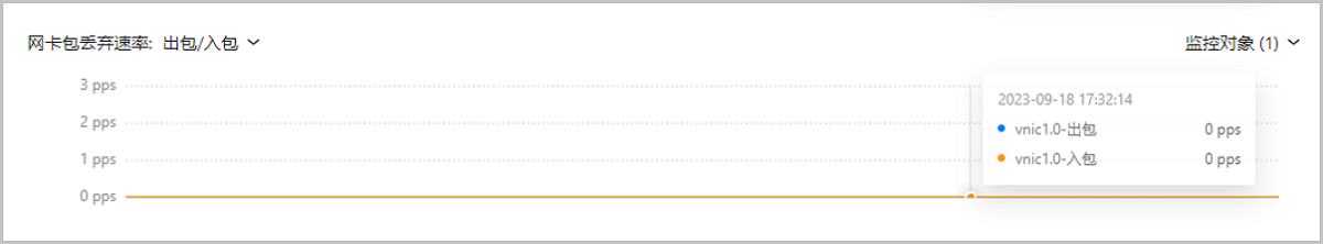
Internal Monitoring
The Internal Monitoring tab displays the VM performance data, such as the CPU, memory, and disk capacity, obtained by the internal monitoring agent from a host. These data is displayed dynamically in real time through graphs.
Monitoring Mechanism
- The internal monitoring data is obtained by the internal monitoring agent. To view the data, install an agent in advance. You can install GuestTools to install the internal monitoring agent for a VM instance. For detailed installation method, see Installation.
- The obtained data is pushed to the host through the DHCP service of the L3
network or through the QEMU Guest Agent (QGA) contained in the VM
GuestTools.
- If the default network of the VM instance has the DHCP service enabled, the monitoring data is pushed by the DHCP service.
- If the default network of the VM instance has the DHCP service disabled or the DHCP services fails, the monitoring data is then pushed by the QGA. After the DHCP service of the default network is recovered, the monitoring data is switched to be pushed by the DHCP service again.
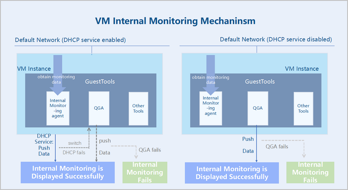 Note:
Note:
- If you use ZStack Cube Ultimate of a version before 4.7.0, you cannot make the monitoring data pushed by the QGA.
- GuestTools for VM instances of certain operating systems does not contain QGA. For detailed information of GuestTools components for different VM operating systems, see 表 1。
Monitoring Data | CPU
- Available time spans: 15 minutes, 1 hour, 6 hours, 1 day, 1 week, 1 month, 1 year, and custom.
- Monitoring metrics:
- CPU Occupancy Rate (System Process): The percentage of CPUs occupied by the current kernel space of the VM instance.
- CPU Occupancy Rate (User Process): The percentage of CPUs occupied by the current user process of the VM instance.
- CPU Occupancy Rate (Waiting): The percentage of CPUs used for waiting for the I/O operations of the VM instance.
- CPU Idle Rate: The percentage of idle CPUs of the VM instance.
- CPU Utilization: The percentage of used CPUs of the VM instance.
- Monitoring object:
- Select All: Display the average, real-time utilization of all CPUs of a VM instance and the utilization of a single CPU.
- Average: Display the average, real-time utilization of all CPUs of a VM instance.
- Single CPU: Display the real-time utilization of a single CPU, such as CPU No. 1, No.2, and No. 3.
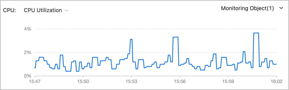
Monitoring Data | Memory
- Available time spans: 15 minutes, 1 hour, 6 hours, 1 day, 1 week, 1 month, 1 year, and custom.
- Monitoring metrics:
- used: The used memory of a VM instance.
- available: The available memory of a VM instance.
- free: The idle memory of a VM instance.
- total: The total memory of a VM instance.
- freeutilization: The percentage of idle memory of a VM instance.
- usedutilization: The percentage of the used memory of a VM instance.
Note: For Windows 7 and Windows Server 2012 VM instances with Memory
Reclaim enabled, the used and total memory displayed here contain the
memory that has been reclaimed to the host.
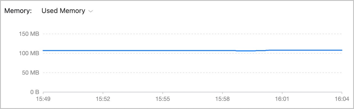 Note: For memory data, internal monitoring is more accurate than external monitoring. We
recommend that you use internal monitoring to monitor the memory data.
Note: For memory data, internal monitoring is more accurate than external monitoring. We
recommend that you use internal monitoring to monitor the memory data.Monitoring Data | Disk Capacity
- Available time spans: 15 minutes, 1 hour, 6 hours, 1 day, 1 week, 1 month, 1 year, and custom.
- Monitoring metrics:
- Disk Utilization: The percentage of used disk of a VM instance.
- Disk Used Capacity: The used capacity of the VM disk.
- Disk Idle Rate: The percentage of idle disk capacity of a VM instance.
- Disk Idle Capacity: The idle disk capacity of a VM instance.
- Monitoring object:
- Select All: Display the real-time status of all disk partitions.
- Single disk partition: Display the real-time read/write status of a single disk partition, such as the vda partition.
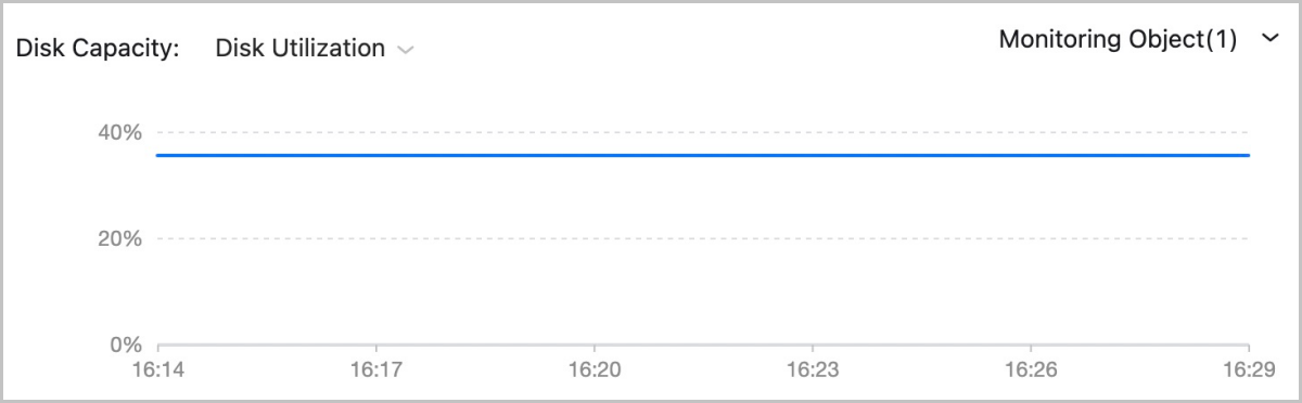
Manage Internal Monitoring
- Stop the agent service:
service zwatch-vm-agent stop. - Start the agent service:
service zwatch-vm-agent
                        start
. - Restart the agent service:
service zwatch-vm-agent
                        restart
. - Query the agent service:
service zwatch-vm-agent
                        status
.
Uninstall Internal Monitoring Agent
- Linux-based VM instances
- Stop the agent by running the service zwatch-vm-agent stop command.
- Delete the service configuration file by running the rm -f /etc/systemd/system/zwatch-vm-agent.service command.
- Delete the agent installation directory by running the rm -rf /usr/local/zstack/zwatch-vm-agent command.
- Windows-based VM instances
- Delete registry related entries.Run the Windows command prompt as an administrator and run the following command to delete the relevant keys in the system:
reg delete HKEY_LOCAL_MACHINE\SYSTEM\CurrentControlSet\Services\MSDTC /f reg delete HKEY_LOCAL_MACHINE\SOFTWARE\Microsoft\MSDTC /f reg delete HKEY_CLASSES_ROOT\CID /f - Stop and reinstall msdtc service.Run the Windows command prompt as an administrator and run the following commands to stop and reinstall the msdtc service:
net stop msdtc msdtc -uninstall msdtc -install - Reboot the VM instance.
- Uninstall the agent.Run the Windows command prompt as an administrator and run the following command to delete the agent:
msiexec /a "c:\Program Files\GuestTools\qemu-ga.msi" targetdir="c:\Program Files"
"c:\Program Files\QEMU Guest Agent\Qemu-ga\qemu-ga.exe" -s vss-uninstall
- Delete registry related entries.
vNUMA Configuration
vNUMA Configuration: vNUMA uses CPU pinning to passthrough the topology of associated host physical NUMA (pNUMA) nodes to a VM instance, generating a topology of virtual NUMA (vNUMA) nodes for the VM instance. This topology enables a vCPU on a vNUMA node to primarily access the local memory and thus improves VM performance.
Concepts
- NUMA: Non-uniform memory access (NUMA) is a computer memory design where the memory access time depends on the memory location relative to the CPU. Under NUMA, a processor can access its own local memory faster than non-local memory and thus improves VM performance.
- pNUMA node: A pNUMA node (physical NUMA node) is a host NUMA node predefined based on the host NUMA architecture. It is used to manage the CPUs and memory of the host. A pNUMA node mainly consists of pCPUs and local memory.
- pNUMA topology: A pNUMA topology (physical NUMA topology) is the topology of the host NUMA nodes predefined by the CPU vendor based on the host NUMA architecture.
- vNUMA node: A vNUMA node (virtual NUMA node) is generated by passing-through associated pNUMA nodes via CPU pinning. It is used to manage the CPUs and memory of a VM instance. A vNUMA node mainly consists of vCPUs and local memory.
- vNUMA topology: A vNUMA topology (virtual NUMA topology) is the topology of VM NUMA nodes generated by passing-through associated pNUMA nodes via CPU pinning.
- Local memory: Local memory is the memory that a CPU (pCPU or vCPU) accesses through the Uncore iMC (Integrated Memory Controller) of the same NUMA (pNUMA or vNUMA) node. Compared with accessing non-local memory, accessing local memory has lower latencies.
Fundamentals
vNUMA configurations are achieved through CPU pinning, which assigns the vCPUs of a VM instance to specific pCPUs of the host. In vNUMA configurations, all vCPUs of the VM instance are pinned to pCPUs of the host. In addition, the pCPUs pinned by a vCPU belong to the same pNUMA node.
After the vNUMA configurations are completed, a vNUMA topology with one or more vNUMA nodes is generated by passing-through the topology of associated host pNUMA nodes. Then the vCPUs of the VM instance primarily access the local memory of the vNUMA node where the vCPUs reside.
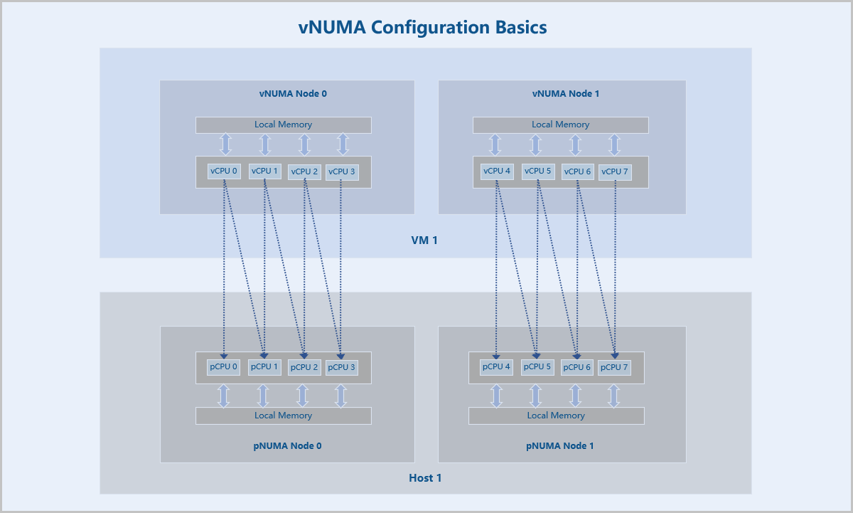
Configure vNUMA
Note: vNUMA groups vCPUs and memory based on the CPU pinning
configurations. Before you can configure vNUMA, you need to disable the advanced
setting Instance Offering Online Modification and Memory Balloon
of the VM instance.- vNUMA: Choose whether to enable vNUMA. By default, vNUMA is disabled.
- CPU
Pinning: CPU pinning assigns the vCPUs of a VM instance to
specific host pCPUs. Two CPU pinning methods are supported: By NUMA Topology
and By Entry.
- By NUMA Topology: This method indicates that
you pin vCPUs to pCPUs based on the host pNUMA topology. You can
implement Manual Pinning or Smart Pinning.
- Manual Pinning allows you to customize vCPU-pCPU binding for all vCPUs.
- Smart Pinning assigns a vCPU of a VM instance to a pCPU on a host pNUMA node by descending order of the pNUMA node ID. If all pCPUs on the pNUMA node are pinned, a pCPU on the next pNUMA node is to be pinned. If all pCPUs of the host are pinned but some vCPUs are not assigned to pCPUs, each vCPU is assigned to a pCPU starting again from the pNUMA node with the maximum node ID.
- You can pin a vCPU to one or more pCPUs or pin one or more vCPUs to a pCPU.
- The utilization of each pCPU in the past 15 minutes is displayed. You can pin a vCPU to the optimal pCPU based on the utilization.
- By Entry:
- You can click Add CPU Pinning to specify more CPU pinning rules.
- Enter the vCPU range in the left text box and the pCPU range
in the right. Note that the - symbol indicates the
value range, while the ^ symbol indicates that a
value is not included. If you specify multiple entries in a
rule, separate each entry by using a comma (,). The
following are some examples:
- 0-2 indicates CPU 0, CPU 1, and CPU 2.
- ^2 indicates that CPU 2 is not included.
- 0-2,^2 indicates CPU 0 and CPU 1.
- 1-7,^2,^3,^4,10 indicates CPU 1, CPU 5, CPU 6, CPU 7, and CPU 10.
Note:
- ZStack Cube Ultimate supports fixed vCPU performance on VM instances.
- All vCPUs of the VM instance must be pinned to pCPUs of the host.
- The pCPUs pinned by a vCPU must belong to the same pNUMA node.
- The vCPU range depends on the selected instance offering of the VM instance, while the pCPU range depends on the number of pCPUs of the host.
- If a vCPU has multiple CPU pinning rules, the union of the rules is used.
- ZStack Cube Ultimate supports CPU overcommitment. Therefore, the number of vCPUs can be greater than that of pCPUs. However, if the number of vCPUs specified in the CPU pinning rule is greater than that of pCPUs, the VM performance will be affected. Therefore, CPU overcommitment is not recommended.
- By NUMA Topology: This method indicates that
you pin vCPUs to pCPUs based on the host pNUMA topology. You can
implement Manual Pinning or Smart Pinning.
- Reboot VM Instance: Choose whether to restart the VM
instance. By default, the VM instance is not restarted.Note:
- You need to restart the VM instance to make the vNUMA configuration take effect.
- Restarting the VM instance may temporarily interrupt the application workloads running on the VM instance. Proceed with caution.
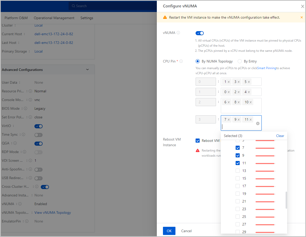
vNUMA Topology
- vNUMA:
- The vCPUs that pin pCPUs residing on the same pNUMA node form a vNUMA node. Therefore, each vNUMA node is associated with a pNUMA node.
- Total Memory: The total amount of local memory that a vCPU can access from the vNUMA node where it resides.
- pNUMA:
- All pNUMA nodes that associate with the VM instance are displayed.
- Total Memory: The total amount of local memory that a pCPU can access from the pNUMA node where it resides.
- Free Memory: The amount of free local memory that a pCPU can access from the pNUMA node where it resides.
- Both the total memory and free memory are measured based on physical hardware resources.
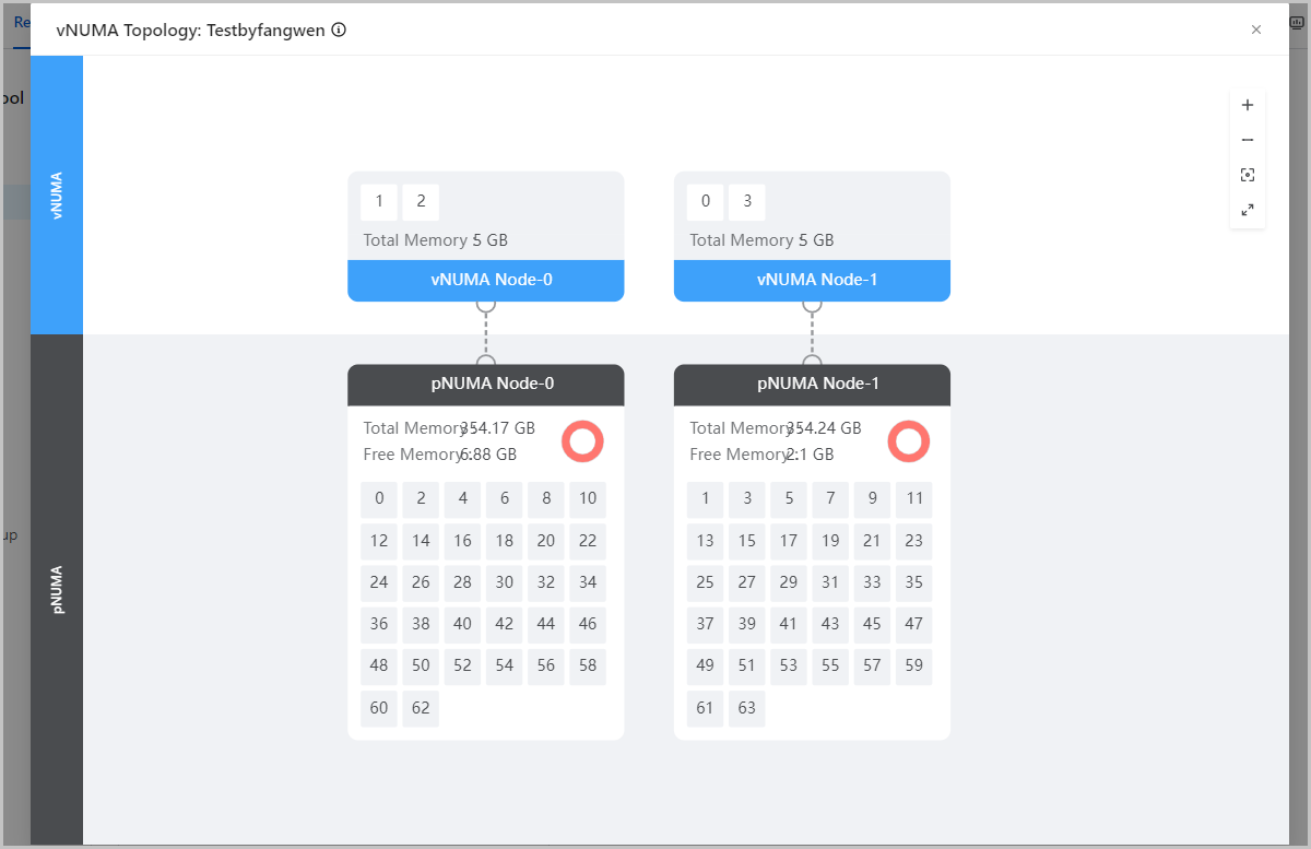
Benefits
- Better System Performance: vNUMA uses CPU pinning to generate a topology of vNUMA nodes for VM instances, which enables a vCPU on a vNUMA node of VM instances to primarily access the local memory and thus improves VM performance.
- Flexible Configuration Methods: Multiple CPU pinning methods make the vNUMA configuration more visualized, intelligent, and convenient. These characteristics allow you to efficiently configure vNUMA that suits your business needs.
Scenarios
- Scenarios that require database and compiling services
Database services such as Oracle and SQL Server and compiling services need to frequently access memory. This requires high performance and fast response of the system. vNUMA enables the services to primarily access local memory and thus greatly reduces latencies and improves computing performance of the system.
- CPU-intensive application scenarios:
CPU-intensive applications have high demand on CPU resources. If many small CPU-intensive applications are running on a VM instance, frequent context switching may occur. vNUMA resolves this issue by assigning vCPUs to specific pCPUs and thus improves system performance.
Limitations
- CPU pinning is not supported for the VM instance (CPU pinning during vNUMA configuration is supported).
- You cannot live modify the instance offering of the VM instance.
- Before you hot migrate the VM instance across hosts, make sure that the pNUMA architecture of the destination host is consistent with that of the source host.
- When you hot migrate the VM instance across hosts and primary storages, the VM instance will be migrated only to a host that has the same pNUMA architecture of the source host.
CPU Pinning
CPU Pinning: CPU pinning assigns the virtual CPUs (vCPUs) of a VM instance to specific physical CPUs (pCPUs) of the host, which improves VM performance.
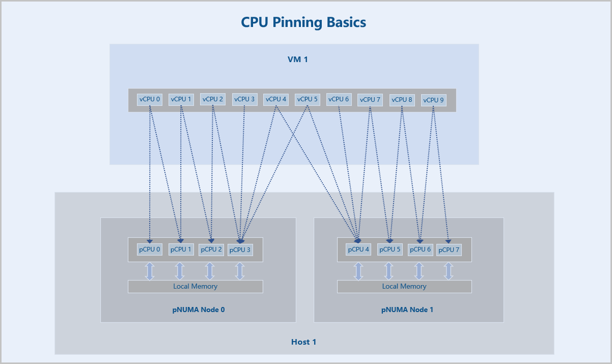
Configure CPU Pinning
Note: Before you can
configure CPU pinning for a VM instance, disable vNUMA for the VM
instance.- CPU
Pinning: CPU pinning assigns the vCPUs of a VM instance to
specific host pCPUs. Two CPU pinning methods are supported: By NUMA Topology
and By Entry.
-
- By NUMA Topology: This method indicates that
you pin vCPUs to pCPUs based on the host pNUMA topology. You can
implement Manual Pinning or Smart Pinning.
- Manual Pinning allows you to customize vCPU-pCPU binding for all vCPUs.
- Smart Pinning assigns a vCPU of a VM instance to a pCPU on a host pNUMA node by descending order of the pNUMA node ID. If all pCPUs on the pNUMA node are pinned, a pCPU on the next pNUMA node is to be pinned. If all pCPUs of the host are pinned but some vCPUs are not assigned to pCPUs, each vCPU is assigned to a pCPU starting again from the pNUMA node with the maximum node ID.
- You can pin a vCPU to one or more pCPUs or pin one or more vCPUs to a pCPU.
- The utilization of each pCPU in the past 15 minutes is displayed. You can pin a vCPU to the optimal pCPU based on the utilization.
- By Entry:
- You can click Add CPU Pinning to specify more CPU pinning rules.
- Enter the vCPU range in the left text box and the pCPU range
in the right. Note that the - symbol indicates the
value range, while the ^ symbol indicates that a
value is not included. If you specify multiple entries in a
rule, separate each entry by using a comma (,). The
following are some examples:
- 0-2 indicates CPU 0, CPU 1, and CPU 2.
- ^2 indicates that CPU 2 is not included.
- 0-2,^2 indicates CPU 0 and CPU 1.
- 1-7,^2,^3,^4,10 indicates CPU 1, CPU 5, CPU 6, CPU 7, and CPU 10.
- By NUMA Topology: This method indicates that
you pin vCPUs to pCPUs based on the host pNUMA topology. You can
implement Manual Pinning or Smart Pinning.
Note:
- The vCPU range depends on the selected instance offering of the VM instance, while the pCPU range depends on the number of pCPUs of the host.
- If a vCPU has multiple CPU pinning rules, the union of the rules is used.
- ZStack Cube Ultimate supports CPU overcommitment. Therefore, the number of vCPUs can be greater than that of pCPUs. However, if the number of vCPUs specified in the CPU pinning rule is greater than that of pCPUs, the VM performance will be affected. Therefore, CPU overcommitment is not recommended.
-
- Reboot VM Instance: Choose whether to restart the VM
instance. By default, the VM instance is not restarted.Note:
- You need to restart the VM instance to make the CPU pinning configuration take effect.
- Restarting the VM instance may temporarily interrupt the application workloads running on the VM instance. Proceed with caution.
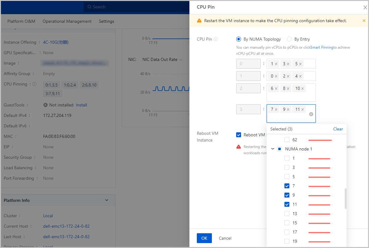
Benefits
- Better System Performance: CPU pinning assigns the vCPUs of a VM instance to specific host pCPUs, which makes full of CPU cache and thus improves VM performance and operating efficiencies.
- Flexible Configuration Methods: Multiple CPU pinning methods make the configuration more visualized, intelligent, and convenient. These characteristics allow you to efficiently configure CPU pinning that suits your business needs.
Scenarios
- CPU-intensive application scenarios:
CPU-intensive applications have high demand on CPU resources. If many small CPU-intensive applications are running on a VM instance, frequent context switching may occur. CPU pinning resolves this issue by assigning vCPUs to specific pCPUs and thus improves system performance.
- Unbalanced CPU usage scenarios:
If many applications are using one or more specific pCPUs, you can configure CPU pinning to adjust CPU usage in a more balanced way.
Limitations
- Cloning or migrating a VM instance also copies the CPU pinging rule, while creating a VM image or performing VM backup does not.
- When you power off a VM instance and modify its instance offering by reducing the number of its vCPUs, the CPU pinning rules that relate to the reduced vCPUs no longer take effect. In this case, we recommend that you modify or delete these rules.
EmulatorPin Configuration
EmulatorPin Configuration: EmulatorPin assigns all other threads than virtual CPU (vCPU) threads and IO threads of a VM instance to physical CPUs (pCPUs) of the host so that these threads run on assigned pCPUs.
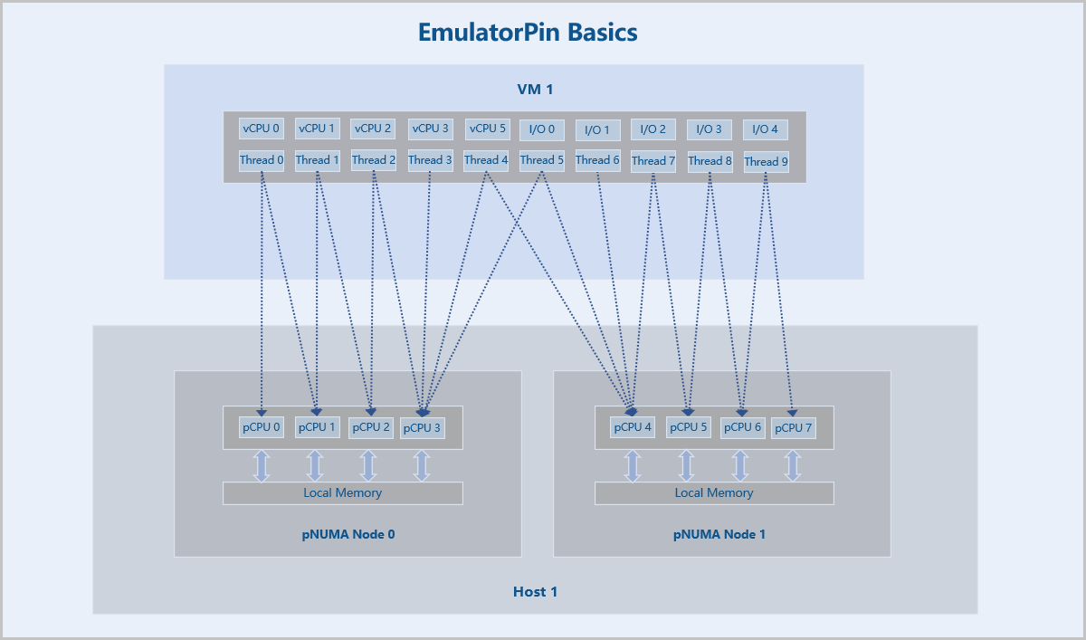
Configure EmulatorPin
On the main menu of ZStack Cube Ultimate, choose . Select the target VM instance, choose , and go to the Configure EmulatorPin page.
You can configure EmulatorPin by setting the following parameters:
- EmulatorPin: EmulatorPin assigns all other threads than vCPU threads and IO threads of a VM instance to pCPUs of the host. You can configure EmulatorPin by using the pNUMA node of the host.
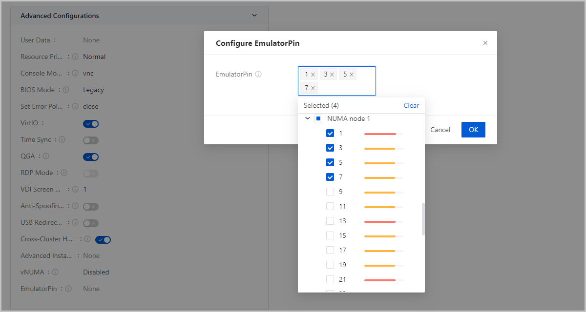
Scenarios
- Concurrent Running of Multiple Applications:
If many VM instances that run different applications are running on a host, context switching may occur. EmulatorPin assigns main QEMU threads of a VM instance to specific pCPUs. This isolates the main threads of VM instances and thus ensures relative stability of the system.
NIC Monitoring
The NIC monitoring data of a VM instance is obtained from the host by using libvirt and is displayed through cards and curve charts.
View NIC Monitoring Data
On the details page of a VM instance, click the Configuration Info tab and select the NIC. On the NIC list, click on the name of a NIC. Then, the NIC details page appears. left side to access the NIC list. Click on the NIC name. Then, NIC details page appears. On the NIC details page, you can see the basic information and the monitoring data.
- The cards show the total traffic, average/maximum data rate, and the 95th
percentile of data sent or received by a NIC in the selected time span.
- Total traffic: The total amount of data sent or received by a NIC.
- Average data rate: The average amount of data sent or received per second by a NIC.
- Maximum data rate: The maximum value of the average data rate. The average data rate is calculated every 5 minutes.
- 95th percentile: This value is calculated by arranging the average data rate samples collected every 5 minutes in the selected time range in descending order, and removing all values greater than the highest 5% of the data.
图 1. Monitoring Data on Cards 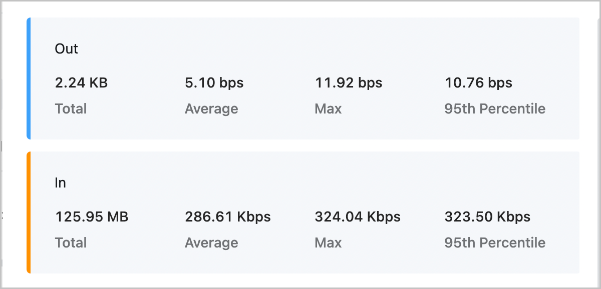
- The curve charts show the real-time NIC data rate and packet rate in the
selected time span.
- NIC data rate: The number of data bits sent or received by a NIC per second.
- NIC packet rate: The number of data packets sent or received by a NIC per second.
图 2. Monitoring Data on Curve Charts 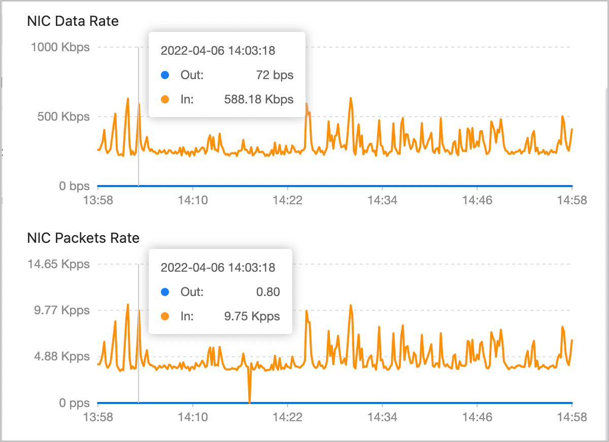
Resize the Root Volume
ZStack Cube Ultimate allows you to resize the root volume of a VM instance when the VM instance is in the running or stopped state. Note that only increasing volume size is supported.
Resize the Root Volume
- On the VM Instance management page, select a VM
instance that is in the running or stopped state and choose . Then, the Resize Root Volume dialog box
is displayed.You can set a new size as needed. The new size takes effect immediately.
图 1. Resize Root Volume 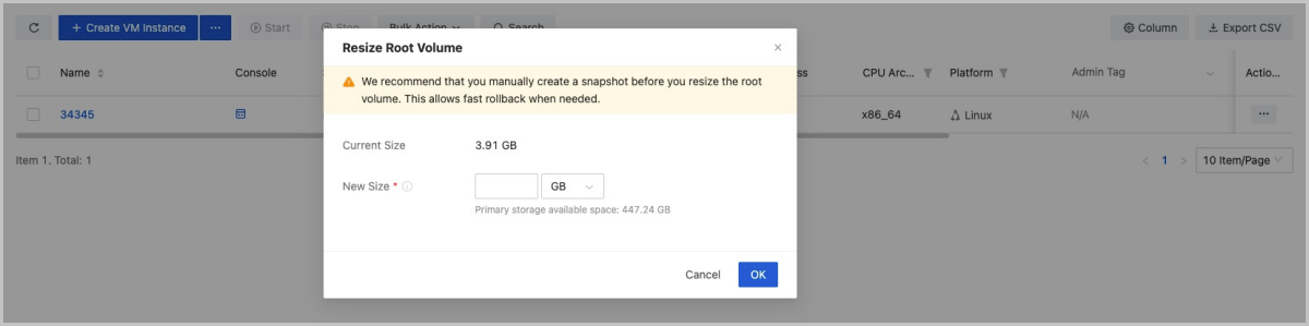
- Select a VM instance that is in the running or stopped state and go to the
details page of the VM instance. On the Configuration
Info tab page, select the root volume to be resized and
choose . Then, the Resize Volume dialog box is
displayed.You can set a new size as needed. The new size takes effect immediately.
图 2. Resize Volume 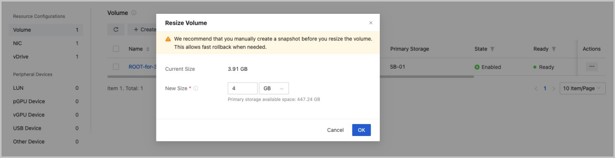
- Select a VM instance that is in the running or stopped state and go to the details page of the VM instance. On the Configuration Info tab page, click on the name of the root volume to be resized and set a new size for the root volume. The new size takes effect immediately.
The steps above only increase the size of the root volume. To make the new size recognized by the VM instance, partition and resize the hard disk in the operating system of the VM instance.
Partition and Resize the Hard Disk
Note:
- Before you resize a root volume, create a snapshot for the VM instance to enhance the data security.
- The resize operation has potential risks. For security reasons, we recommend that you plan a new partition for the new size.
- The resize operation only increases the size, not reduce the size.
- The increased size can be merged into the last partition for continuous
use.
- If the last partition is a system backup partition (Windows), you must plan a new partition for the increased size.
- If the last partition is a swap partition, you can delete the swap partition first, add the increased size to the last partition, and then rebuild a swap partition.
The following are four different resize scenarios.
- Use the GParted open source tool to resize the ext4 root partition for an
instance that has both the ext4 and swap partitions.Note:
- In this scenario, you need to re-plan the current partition by using Live CD.
- To prevent data loss, exercise caution when you adjust a partition.
Assume that VM instance uses an ext4 root partition of 35 GB and a swap partition of 5 GB. The total size is 40 GB. After you resize the root volume from 40 GB to 50 GB, you want to add the increased size to the ext4 root partition.
Procedure:- Add a GParted ISO. You can download the ISO from the GParted official website https://gparted.org/download.php. We recommend that you download the amd64 iso, indicating that 64-bit operating systems are supported.
- After you add the ISO, set CD ROM as the first boot order and Hard Disk as the second. Then, the VM instance boots from CD ROM next time.
- Use GParted Live CD to boot the system and launch the console of the VM instance. After the GParted boot finished, follow the instructions and long-press the Enter key until you enter the graphical interface.
- In the GParted interface, right-click the original swap partition to
delete it, resize ext4 from 35 GB to 46 GB, and create a new swap
partition for the unallocated 4 GB.
图 3. Delete Original swap Partition 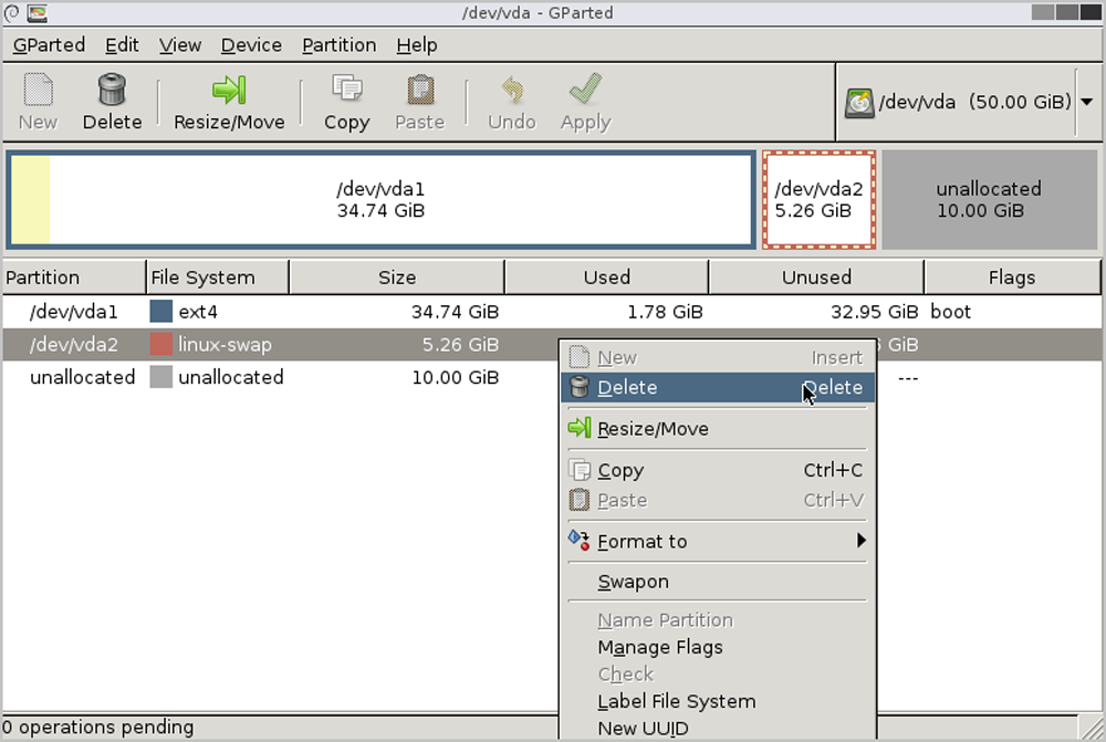
图 4. Resize ext4 from 35 GB 46 GB 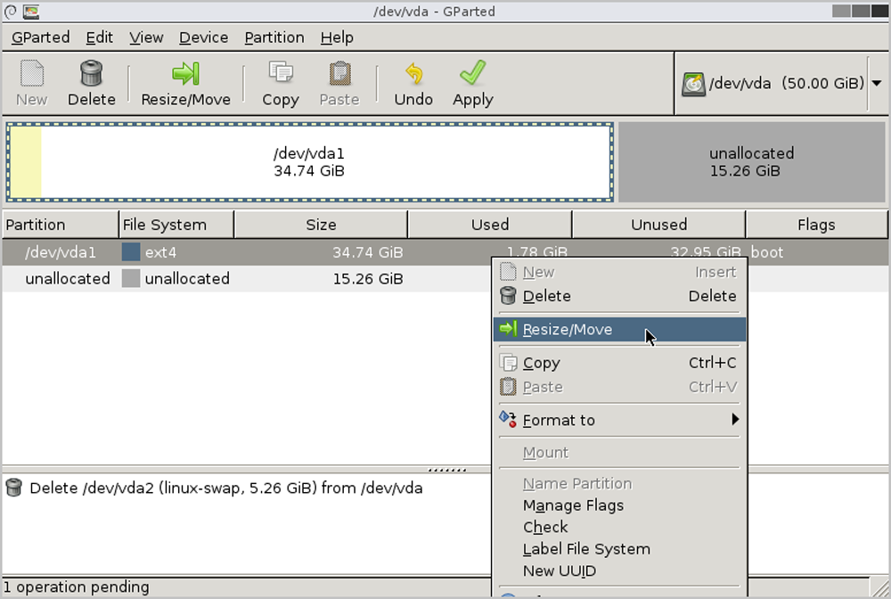
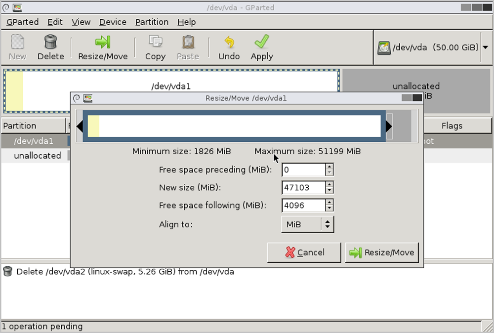
图 5. Create a 4 GB swap Partition 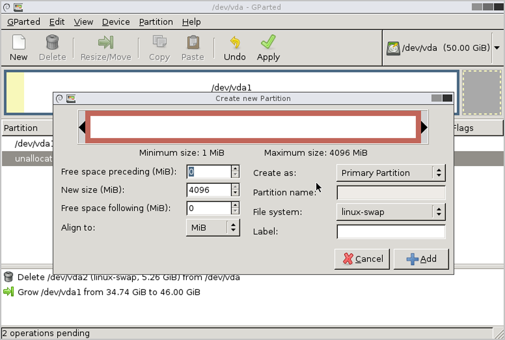
- Power off the VM instance, detach the ISO, and start the VM instance again.
- Launch the VM console and run the
df -hcommand. Then, you can see that the size of the root partition is increased to 46 GB.[root@10-58-21-213 ~]# df -h Filesystem Size Used Avail Use% Mounted on /dev/vda1 46G 1.2G 42G 3% / - Enable the swap partition and modify the
/etc/fstab disk partition
table.
[root@10-58-21-213 ~]# fdisk -l|grep vda Disk /dev/vda: 53.7 GB, 53687091200 bytes, 104857600 sectors /dev/vda1 * 2048 96468991 48233472 83 Linux /dev/vda2 96468992 104857599 4194304 82 Linux swap / Solaris [root@10-58-21-213 ~]# mkswap /dev/vda2 mkswap: /dev/vda2: warning: wiping old swap signature. Setting up swapspace version 1, size = 4194300 KiB no label, UUID=ed99f72b-aafb-43ad-be8f-fcd09794beb0 #You can see that the UUID of the swap partition is ed99f72b-aafb-43ad-be8f-fcd09794beb0. [root@10-58-21-213 ~]# swapon /dev/vda2 #Enable the swap partition. [root@10-58-21-213 ~]# free -m total used free shared buff/cache available Mem: 911 106 671 6 133 657 Swap: 4095 0 4095 [root@10-58-21-213 ~]# sed -i '/swap/d' /etc/fstab echo "UUID=ed99f72b-aafb-43ad-be8f-fcd09794beb0 swap swap defaults 0 0" #Write the swap settings into the disk partition table so that it can be started automatically upon the VM boots. - After you power off and reboot the VM instance, the ext4 partition of the root volume is resized successfully, and the swap partition reserves 4 GB.
- Use the LVM partition tool to resize the LVM partition for
an instance that has both the xfs and swap partitions.Note: This method applies
to the dynamic resizing of LVM partitions without the need of using other
tools.
Assume that the VM instance uses an LVM partition and formats the LVM partition as a boot partition, an xfs root partition, and a swap partition. In this scenario, the size of the xfs root partition and swap partition is 94 GB and 6 GB, respectively. Therefore, the total size is 100 GB. After you resize the root volume from 100 GB to 120 GB, you want to add the increased size to the xfs root partition.
Procedure:- View the current partition and the LVM partition. Here, the size of
the boot partition, LVM partition, and swap partition is 500 MB, 94
GB, and 6 GB, respectively. The boot partition and LVM partition use
/dev/vda1 and
/dev/vda2, respectively. The path of the
LVM partition and swap partition is
/dev/vg/root and
/dev/vg/swap,
respectively.
[root@10-0-44-221 ~]# df -h Filesystem Size Used Avail Use% Mounted on /dev/mapper/vg-root 94G 6.5G 88G 7% / /dev/vda1 477M 104M 344M 24% /boot #The boot partition is 500 MB and uses /dev/vda1. #The LVM partition is 94 GB and uses /dev/vda2. Path: /dev/vg/root. #The swap partition is 6 GB. Path: /dev/vg/swap. [root@10-0-44-221 ~]# fdisk -l |grep vda Disk /dev/vda: 128.8 GB, 128849018880 bytes, 251658240 sectors /dev/vda1 * 2048 1026047 512000 83 Linux /dev/vda2 1026048 209715199 104344576 8e Linux LVM [root@10-0-44-221 ~]# pvdisplay |egrep "Name|Size" PV Name /dev/vda2 VG Name vg PV Size 99.51 GiB / not usable 3.00 MiB PE Size 4.00 MiB #The physical volume uses /dev/vda2. [root@10-0-44-221 ~]# vgdisplay |egrep "Name|Size" VG Name vg VG Size 99.51 GiB PE Size 4.00 MiB alloc PE / Size 25463 / 99.46 GiB Free PE / Size 11 / 44.00 MiB #The volume group information. Name: vg. This volume group will be resized. [root@10-0-44-221 ~]# lvdisplay |egrep "Name|Size" LV Name root VG Name vg LV Size 93.59 GiB LV Name swap VG Name vg LV Size 5.88 GiB #The logical volume information. - After the resizing, run the
fdisk /dev/vdacommand to partition the increased size, create a new partition by usingn, set the new partition to LVM format by usingt, and make the setting take effect by usingw. To make the setting take effect immediately, run thepartprobecommand.[root@10-0-44-221 ~]# fdisk /dev/vda Welcome to fdisk (util-linux 2.23.2). Changes will remain in memory only, until you decide to write them. Be careful before using the write command. Command (m for help): p Disk /dev/vda: 128.8 GB, 128849018880 bytes, 251658240 sectors Units = sectors of 1 * 512 = 512 bytes Sector size (logical/physical): 512 bytes / 512 bytes I/O size (minimum/optimal): 512 bytes / 512 bytes Disk label type: dos Disk identifier: 0x0008168e Device Boot Start End Blocks Id System /dev/vda1 * 2048 1026047 512000 83 Linux /dev/vda2 1026048 209715199 104344576 8e Linux LVM Command (m for help): n Partition type: p primary (2 primary, 0 extended, 2 free) e extended Select (default p): Using default response p Partition number (3,4, default 3): First sector (209715200-251658239, default 209715200): Using default value 209715200 Last sector, +sectors or +size{K,M,G} (209715200-251658239, default 251658239): Using default value 251658239 Partition 3 of type Linux and of size 20 GiB is set Command (m for help): t Partition number (1-3, default 3): Hex code (type L to list all codes): 8e Changed type of partition 'Linux' to 'Linux LVM' Command (m for help): p Disk /dev/vda: 128.8 GB, 128849018880 bytes, 251658240 sectors Units = sectors of 1 * 512 = 512 bytes Sector size (logical/physical): 512 bytes / 512 bytes I/O size (minimum/optimal): 512 bytes / 512 bytes Disk label type: dos Disk identifier: 0x0008168e Device Boot Start End Blocks Id System /dev/vda1 * 2048 1026047 512000 83 Linux /dev/vda2 1026048 209715199 104344576 8e Linux LVM /dev/vda3 209715200 251658239 20971520 83 Linux LVM Command (m for help): w The partition table has been altered! Calling ioctl() to re-read partition table. WARNING: Re-reading the partition table failed with error 16: Device or resource busy. The kernel still uses the old table. The new table will be used at the next reboot or after you run partprobe(8) or kpartx(8) Syncing disks. [root@10-0-44-221 ~]# partprobe - Create a physical volume for the newly formatted
partition.
[root@10-0-44-221 ~]# pvcreate /dev/vda3 Physical volume "/dev/vda3" successfully created #Create a physical volume. - Extend the volume
group.
[root@10-0-44-221 ~]# vgextend vg /dev/vda3 Volume group "vg" successfully extended #Name of the volume group: vg. The new partition will be added to the volume group vg. - Disable the swap partition and delete the original swap logical
volume.
[root@10-0-44-221 ~]# swapoff -a [root@10-0-44-221 ~]# lvremove /dev/vg/swap Do you really want to remove active logical volume swap? [y/n]: yes Logical volume "swap" successfully removed - Add 20 GB to the logical volume
/dev/vg/root.
[root@10-0-44-221 ~]# lvextend -L +20G /dev/vg/root Size of logical volume vg/root changed from 93.59 GiB (23959 extents) to 113.59 GiB (29079 extents). Logical volume root successfully resized. #Add 20 GB to /dev/vg/root. [root@10-0-44-221 ~]# lvdisplay --- Logical volume --- LV Path /dev/vg/root LV Name root VG Name vg LV UUID UkyCVW-gd5E-Z4Q2-bVHv-T84e-c3GH-ZMiUdF LV Write Access read/write LV Creation host, time localhost, 2017-07-26 13:18:40 +0800 LV Status available # open 1 LV Size 113.59 GiB Current LE 29079 Segments 2 allocation inherit Read ahead sectors auto - currently set to 8192 Block device 253:0 - Run the
xfs_growfscommand to resize the XFS file system, make the new size take effect, and check the new partition.[root@10-0-44-221 ~]# xfs_growfs /dev/vg/root meta-data=/dev/mapper/vg-root isize=256 agcount=4, agsize=6133504 blks = sectsz=512 attr=2, projid32bit=1 = crc=0 finobt=0 data = bsize=4096 blocks=24534016, imaxpct=25 = sunit=0 swidth=0 blks naming =version 2 bsize=4096 ascii-ci=0 ftype=0 log =internal bsize=4096 blocks=11979, version=2 = sectsz=512 sunit=0 blks, lazy-count=1 realtime =none extsz=4096 blocks=0, rtextents=0 data blocks changed from 24534016 to 29776896 [root@10-0-44-221 ~]# df -h|grep vg-root Filesystem Size Used Avail Use% Mounted on /dev/mapper/vg-root 114G 6.5G 108G 6% / #Resizing of the new partition takes effect. - Divide a new size from the logical volume group to the swap
partition, enable the swap partition, and write the disk
configuration.
[root@10-0-44-221 ~]# lvcreate -L 4G -n swap vg Logical volume "swap" created. #Create a 4 GB partition named swap from the volume group vg. [root@10-0-44-221 ~]# mkswap /dev/vg/swap Setting up swapspace version 1, size = 4194300 KiB no label, UUID=bfc8a843-c758-4665-adfe-e32752ceda44 #Create a swap partition. Here, you can see that the UUID of the swap partition is bfc8a843-c758-4665-adfe-e32752ceda44. [root@10-0-44-221 ~]# swapon /dev/mapper/vg-swap #Enable the swap partition. [root@10-58-21-213 ~]# sed -i '/swap/d' /etc/fstab echo "UUID=bfc8a843-c758-4665-adfe-e32752ceda44 swap swap defaults 0 0" #Write the swap settings into the disk partition table so that the swap partition can be enabled automatically after the VM instance is started. - After you power off and reboot the VM instance, the XFS system of the VM LVM partition is resized successfully, and the swap partition reserves 4 GB.
- View the current partition and the LVM partition. Here, the size of
the boot partition, LVM partition, and swap partition is 500 MB, 94
GB, and 6 GB, respectively. The boot partition and LVM partition use
/dev/vda1 and
/dev/vda2, respectively. The path of the
LVM partition and swap partition is
/dev/vg/root and
/dev/vg/swap,
respectively.
- Use the growpart tool to extend the xfs root partition instance.Note: This
method applies to the dynamic resizing of xfs partitions without the need of
attaching an ISO or using an LVM partition tool.
Assume that the size of the xfs root partition is 6 GB and the total root volume size is 8 GB. After you resize the root volume from 8 GB to 40 GB, you want to add the increased size to the xfs root partition.
Procedure:- View the current partition. You can see that the root volume is
resized to 40 GB, of which the xfs root partition is 6 GB. The extra
disk space is unallocated and is not added to the disk
partition.
[root@10-0-44-210 ~]# lsblk NAME MAJ:MIN RM SIZE RO TYPE MOUNTPOINT sda 8:0 0 400G 0 disk └─sda1 8:1 0 400G 0 part /mnt/nfs-data vda 253:0 0 40G 0 disk ├─vda1 253:1 0 2G 0 part [SWAP] └─vda2 253:2 0 6G 0 part / - Install the growpart
tool.
[root@10-0-44-210 ~]# yum install -y cloud-utils-growpart - Resize the xfs root partition by using the
growpart <DeviceName>
                                    <PartionNumber>
command. Here, the DeviceName of the xfs root partition is /dev/vda and PartionNumber is2.[root@10-0-44-210 ~]# growpart /dev/vda 2 CHANGED: partition=2 start=4196352 old: size=12580864 end=16777216 new: size=79689695 end=83886047 - View the partitions. Then, you can see that the xfs root partition
is resized from 6 GB to 38
GB.
[root@10-0-44-210 ~]# lsblk NAME MAJ:MIN RM SIZE RO TYPE MOUNTPOINT sda 8:0 0 400G 0 disk └─sda1 8:1 0 400G 0 part /mnt/nfs-data vda 253:0 0 40G 0 disk ├─vda1 253:1 0 2G 0 part [SWAP] └─vda2 253:2 0 38G 0 part / - Extend the XFS file system.
- To extend the XFS file system, make sure that the xfsprogs
tool is installed. The installation command is as
follows:
[root@10-0-44-210 ~]# yum install xfsprogs - Extend the file system in /dev/vda2 by
running the
xfs_growfscommand. Here, / is the mount point.[root@10-0-44-210 ~]# xfs_growfs / meta-data=/dev/vda2 isize=256 agcount=26, agsize=393152 blks = sectsz=512 attr=2, projid32bit=1 = crc=0 finobt=0 spinodes=0 data = bsize=4096 blocks=9961211, imaxpct=25 = sunit=0 swidth=0 blks naming =version 2 bsize=4096 ascii-ci=0 ftype=0 log =internal bsize=4096 blocks=2560, version=2 = sectsz=512 sunit=0 blks, lazy-count=1 realtime =none extsz=4096 blocks=0, rtextents=0 data blocks changed from 1572608 to 9961211 - Check whether the file system reflects the increased volume
size.
[root@10-0-44-210 ~]# df -h /
Filesystem      Size  Used Avail Use% Mounted on
/dev/vda2        38G  3.3G   35G   9% /
- To extend the XFS file system, make sure that the xfsprogs
tool is installed. The installation command is as
follows:
Note: We recommend that you install the expansion and formatting tools
according to the actual operating system. For example,- For CentOS 7, install the following
tool:
yum install cloud-utils-growpart yum install xfsprogs - For Ubuntu 14, Ubuntu 16, Ubuntu 18, and Debian 9, install the
following
tool:
apt install cloud-guest-utils apt install xfsprogs - For Debian 8, openSUSE 42.3, openSUSE 13.1, and SLES 12 SP2, use the growpart or xfsprogs tool of the upstream version.
- View the current partition. You can see that the root volume is
resized to 40 GB, of which the xfs root partition is 6 GB. The extra
disk space is unallocated and is not added to the disk
partition.
- Resize the Windows partitions.You can resize disks of Windows partitions on the disk management page.Note: After you resize the disk of a Windows
partition, scan the disk to take effect.