Hardware
Zone
What is Zone?
A zone is a logical group of resources such as clusters, L2 networks, and primary storage. Zone is the largest resource scope defined in the Cloud.
Basics
- In a data center, a zone corresponds to an equipment room.
- A zone defines a visible boundary. Sub-resources within the same zone are visible mutually and can form a certain relationship. However, sub-resources within different zones are invisible mutually and cannot form mutual relationships.
Characteristics
- Zone isolation:
Isolates physical sub-resources such as primary storage and hosts in different zones, ensuring stability and fault tolerance to the maximum extent.
Reduces network delay and allows for faster access.
- Resource management:
You can set a platform administrator for each zone. A platform administrator can manage one or more zones.
The resources of each project can belong to only one zone.
- Global view:
After you plan a zone, you can view all the resources in the zone on a dedicated dashboard. You can view the resource usage by KVM or vCenter.
Considerations
- Hosts in the same physical layer 2 broadcast domain must be in the same zone. These hosts can be grouped as one or more clusters.
- A physical layer 2 broadcast domain cannot span multiple zones. Instead, it must be mapped as an L2 network in a single zone.
- A primary storage cannot span multiple zones. Instead, it must be mapped as a primary storage in a single zone.
- A data center can have multiple zones.
- A zone can have one or more image storage attached.
- Resources in a zone, such as a primary storage, can only access the image storage attached to the zone.
- An image storage can be deleted from a zone. After the image storage is deleted, resources in the zone will not see the image storage any more.
- If an image storage is no longer accessible to resources of a zone due to network typology changes in a data center, you can detach the image storage from this zone.
- To better manage the relationship between image storage and zone, the UI specifies that an image storage can only be attached to one zone at a time. That is, an image storage that has been attached to a zone cannot be reattached to the other zone. When you add an image storage in the UI, the image storage will be automatically attached to the current zone. When you delete a zone, you will directly delete the image storage attached to the zone.
Create a Zone
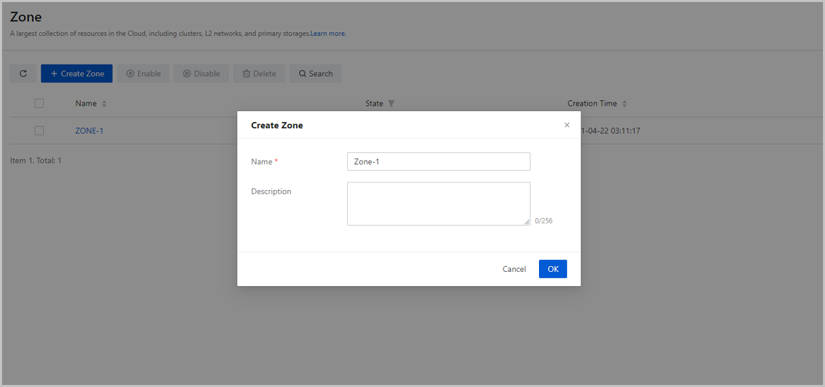
On the main menu of ZStack Cloud, choose . On the Zone page, click Create Zone. Then, the Create Zone page is displayed.
- Name: Enter a name for the zone.
- Description: Optional. Enter a description for the zone.
Manage a Zone
On the main menu of ZStack Cloud, choose . Then, the Zone page is displayed.
The following table lists the actions that you can perform on a zone.
| Action | Description |
|---|---|
| Create Zone | Create a zone. |
| Edit Zone | Edit the name and description of the zone. |
| Enable Zone | Enable a disabled zone. |
| Disable Zone | Disable a enabled zone. Note: Note:
|
| Set as Default Zone | Set a zone as the default zone.Note:
|
| Delete Zone | Delete a zone.Note: Deleting a zone also deletes the clusters,
hosts, networks, primary storage, and managed vCenters, and all
sub-resources (such as VPC vRouter) of each resource in the
zone. Please exercise caution. |
Cluster
What is Cluster?
A cluster is a logical group of hosts (compute nodes). In a real data center, a cluster usually maps to a rack.
- All hosts in the same cluster must be installed with the same operating system.
- All hosts in the same cluster must have the same network configuration.
- All hosts in the same cluster must be able to access the same primary storage.
- Before a cluster can provide VM services, the cluster must have a primary storage and an L2 network attached.
- The scale of a cluster, which is the maximum number of hosts that the cluster can contain, is not limited.
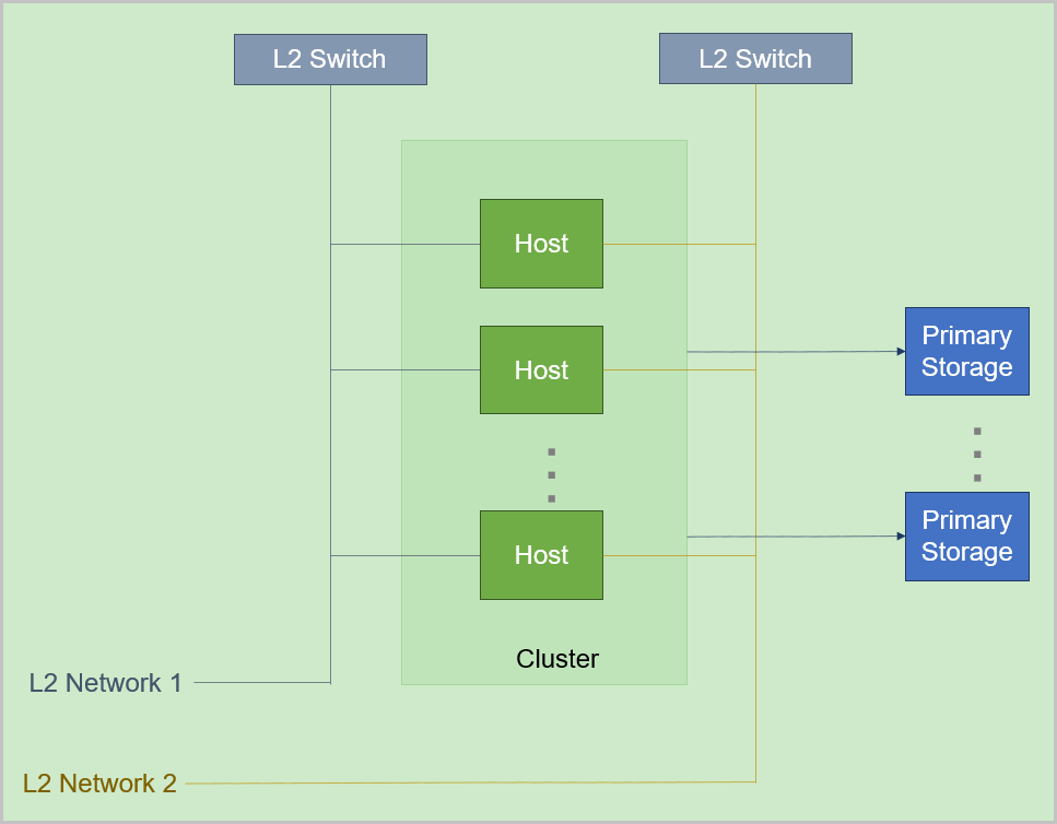
The relationship between a typical cluster and its associated resources is as follows:
Cluster | Zone
You can create more than one cluster in a zone, and allocate newly created hosts to different clusters as needed.
Cluster | Primary Storage and L2 Network
 Note:
Note:
- Cluster | Primary Storage
- A primary storage can be attached to one or more clusters.
- A cluster can have one or more primary storage attached.The following are primary storage of the same type that a cluster can have:
- A cluster can have one or more LocalStorage primary storage attached.
- A cluster can have one or more NFS primary storage attached.
- A cluster can have one or more SharedBlock primary storage attached.
- A cluster can have one SharedMountPoint (SMP) primary storage attached.
- A cluster can have only one Ceph primary storage attached.
- A cluster can have only one Vhost primary storage attached.
- A cluster can have only one CBD primary storage attached.
- A cluster can have only one AliyunNAS primary storage attached.
- A cluster can have only one AliyunEBS primary storage attached.
The following are combinations of primary storages that a cluster can have:- A cluster can have both a LocalStorage and an NFS primary storage attached.
- A cluster can have both a LocalStorage and an SMP primary storage attached.
- A cluster can have both multiple LocalStorage and multiple SharedBlock primary storage attached.
- A cluster can have both a Ceph and a maximum of three LocalStorage primary storage attached.
- A cluster can have both a Ceph and a SharedBlock primary storage attached.
- A cluster can have both a Ceph and more than one SharedBlock primary storage attached.
- A cluster can have both a Ceph and multiple NFS primary storage attached.
- A cluster can have both multiple NFS and multiple SharedBlock primary storage attached.
-
A cluster can have both a CBD and multiple SharedBlock primary storage attached.
-
A cluster can have both a CBD and multiple Local Storage primary storage attached.
-
A cluster can have both a CBD and a Ceph primary storage attached.
-
A cluster can have both a Vhost and multiple SharedBlock primary storage attached.
The following table lists the relationship between a primary storage and a cluster.Primary Storage Cluster LocalStorage A cluster can have one or more LocalStorage primary storage attached. NFS A cluster can have one or more NFS primary storage attached. SharedBlock A cluster can have one or more SharedBlock primary storage attached. SMP A cluster can have one SMP primary storage attached. Ceph A cluster can have only one Ceph primary storage attached. Vhost A cluster can have only one Vhost primary storage attached. CBD A cluster can have only one CBD primary storage attached. AliyunNAS A cluster can have only one AliyunNAS primary storage attached. AliyunEBS A cluster can have only one AliyunEBS primary storage attached. LocalStorage + NFS A cluster can have one LocalStorage and one NFS primary storage attached. LocalStorage + SMP A cluster can have one LocalStorage and one SMP primary storage attached. LocalStorage + SharedBlock A cluster can have multiple LocalStorage and multiple SharedBlock primary storage attached. Ceph + LocalStorage A cluster can have both a Ceph and a maximum of three LocalStorage primary storage attached. Ceph + SharedBlock - A cluster can have one Ceph and one SharedBlock primary storage attached.
- A cluster can have one Ceph and multiple SharedBlock primary storage attached.
Ceph + NFS A cluster can have both a Ceph and multiple NFS primary storage attached. NFS + SharedBlock A cluster can have both multiple NFS and multiple SharedBlock primary storage attached. CBD + Shared Block A cluster can have both a CBD and multiple SharedBlock primary storage attached.
CBD + Local Storage A cluster can have both a CBD and multiple Local Storage primary storage attached.
CBD + Ceph A cluster can have both a CBD and a Ceph primary storage attached.
Vhost + Shared Block A cluster can have both a Vhost and multiple SharedBlock primary storage attached.
- When you attach multiple LocalStorage primary storage to a cluster, partition the corresponding URLs on the hosts before you add hosts and primary storage, and make sure that each LocalStorage is deployed on an exclusive logical volume or physical disk.
- A primary storage can be accessed by all hosts in the cluster to which the primary storage belongs.
- If a primary storage cannot be accessed by hosts in the cluster due to network typology changes in the data center, you can detach the primary storage from the cluster.
- Cluster | L2 Network
- A cluster can have one or more L2 networks attached. Also, an L2 network can be attached to one or more clusters.
- A cluster can have a VXLAN pool attached. The VNIs in the VXLAN pool can be used to create different VXLAN networks.
- One NIC can be used to create only one NoVlan network.
- For VLAN networks, different VLAN IDs represent different L2 networks.
- If hosts in a cluster no longer exist in the layer 2 broadcast domain of an L2 network due to network typology changes in the data center, you can detach the L2 network from the cluster.
Cluster | Image Storage
No direct dependency exists between a cluster and an image storage. An image storage can provide services for multiple clusters.
| PS/BS | ImageStore | Ceph |
| LocalStorage | ○ | × |
| NFS | ○ | × |
| SMP | ○ | × |
| Ceph | ○ | ○ |
| SharedBlock | ○ | × |
| Vhost | ○ | × |
| CBD | ○ | × |
- When primary storage are LocalStorage, NFS, or SMP, the default type for image storage is ImageStore.
- When primary storage are NFS or SMP, you can manually mount the corresponding shared directories to the local directories of the corresponding image storage. In this regard, both primary storage and image storage can use the network shared storage.
- When primary storage is Ceph, you can use the primary storage in the same Ceph cluster as image storage. You can also use the ImageStore primary storage as image storage.
- When primary storage is SharedBlock, the default type for image storage is ImageStore.
- When primary storage is AliyunNAS, the default type for image storage is ImageStore.
- When primary storage is AliyunEBS, the default type for image storage is AliyunEBS.
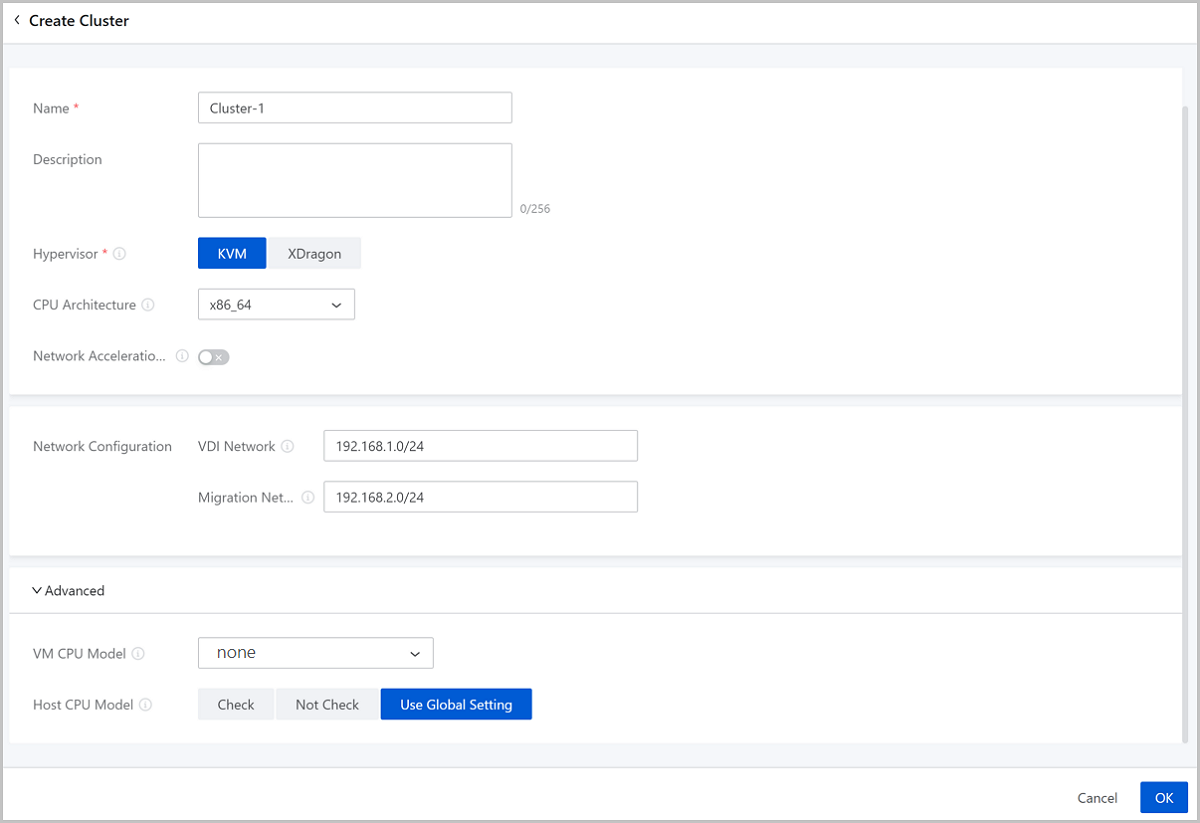
Create a Cluster
On the main menu of ZStack Cloud, choose . On the Cluster page, click Create Cluster. Then, the Create Cluster page is displayed.
- Zone: By default, the current zone is selected.
- Name: Enter a name for the cluster.
The name must be 1 to 128 characters in length and can contain Chinese characters, letters, digits, spaces, hyphens (-), underscores (_), periods (.), parenthesis (), colons (:), and plus signs (+) and cannot begin or end with spaces.
- Description: Optional. Enter a description for the cluster.
- Hypervisor: Select the hypervisor type of the cluster.
You can select KVM or XDragon.
- If you select KVM, make sure that the hosts to be added to the cluster apply the KVM virtualization technology.
- If you select XDragon, make sure that the hosts to be added to the cluster apply the X-Dragon architecture.
- CPU Architecture: Select a CPU architecture for hosts to
be added to the cluster. You can select x86_64, aarch64, mips64el and loongarch64.Note:
- If left blank, the system will specify the CPU architecture of the first host you add to the cluster.
- The CPU architecture cannot be changed after being set. Please select a proper one according to your cloud environment.
- Network Acceleration Support:
Choose whether to enable network acceleration for a cluster. By default, network
acceleration support is disabled.Note:
- If you enable network acceleration support for a cluster, make sure that the L2 network associated with the cluster uses the Smart NIC network acceleration mode and the hosts in the cluster must be attached with smart NICs of the specified model. Otherwise, network acceleration does not work as expected.
- Once you enable network acceleration support, the feature cannot be disabled.
- You can enable network acceleration support only when you create a cluster.
- The network acceleration support feature is supported by KVM clusters but not by XDragon clusters.
- Network Configuration: Configure a dedicated VDI network
or migration network for the cluster.
- VDI Network: Optional. Enter the CIDR of the VDI
network.
- If you deployed a dedicated network for VDI, add the network directly to the Cloud.
- Using a dedicated VDI network can avoid network congestions and improve transmission efficiencies.
- If not set, the VDI will use a management network by default.
- Migration Network: Optional. Enter the CIDR of
the migration network.
- If you deployed a dedicated network for VM migration, add the network directly to the Cloud.
- Using a dedicated migration network can avoid network congestions and improve transmission efficiencies.
- If not set, VM migrations will use a management network by default.
- VDI Network: Optional. Enter the CIDR of the VDI
network.
- Advanced: Make advanced configurations if you selected
the KVM type in the previous steps.
- VM CPU Model: Optional. Specify a CPU model for
VM instances in the cluster.
Cluster CPU Architecture VM CPU Model in Cluster VM CPU Mode in Global Setting Description Note x86_64 Inherit Global Setting (by default) - The CPU model of VM instances in the cluster is consistent with that configured in the global setting.
none (by default) The CPU model of VM instances on the Cloud is simulated via QEMU. In this mode, the VM instances inherit necessary host CPU features to a small degree. You can select this mode if you need to migrate your VM instances. - If you select host-passthrough, VM instances will allow for virtualization. However, if you migrate a VM instance to a host whose CPU model is different from the current host, the migration may fail. In addition, the CPU utilization of the VM instance measured within the instance may differ from the CPU utilization measured from the host.
- Hygon_Customized is virtualized CPU model designed only for compating OS of eariler versions.
- If you specifically set the CPU model of an individual VM instance, the VM CPU model configured for the cluster will not take effect on that VM instance.
- If you specifically set the CPU model for a cluster, the VM CPU model configured in the global setting will not take effect on VM instances in the cluster.
- If you modify the CPU model, you need to restart a VM instance to make the modification take effect.
host-model The CPU model of VM instances on the Cloud is similar to or same as that of the host, such as Haswell Intel CPU. In this mode, VM instances inherit many host CPU features. You can select this mode if you need to migrate VM instances. host-passthrough The CPU model and CPU features of VM instances on the Cloud are the same as the CPU model and CPU features of hosts. For example, both VM instances and hosts support the extended page table extension, huge page, and virtualization features. Compared with the none, host-model, and Custom modes, VM instances in this mode have the most CPU features. You can select this mode if your business requires many features. Custom (a specified CPU model) The VM instances on the Cloud share the specified CPU model. Different CPU models may have different CPU features. Note that if your host CPU is Hygon and the OS of your VM instance is an earlier version such as Windows Server 2012 R2 and Windows Server 2008 R2, you can select Hygon_Customized. none N/A The CPU model of VM instances in the cluster is simulated via QEMU. In this mode, the VM instances inherit necessary host CPU features to a small degree. You can select this mode if you need to migrate your VM instances. host-model N/A The CPU model of VM instances in the cluster is similar to or same as that of the host, such as Haswell Intel CPU. In this mode, VM instances inherit many host CPU features. You can select this mode if you need to migrate VM instances. host-passthrough N/A The CPU model and CPU features of VM instances in the cluster are all the same as the CPU model and CPU features of hosts in the cluster. For example, both VM instances and hosts support the extended page table extension, huge page, and virtualization features. Compared with the none, host-model, and Custom modes, VM instances in this mode have the most CPU features. You can select this mode if your business requires many features. Custom (a specified CPU model) N/A The VM instances in the cluster share the specified CPU model. Different CPU models may have different CPU features. Note that if your host CPU is Hygon and the OS of your VM instance is an earlier version such as Windows Server 2012 R2 and Windows Server 2008 R2, you can select Hygon_Customized. aarch64 host-passthrough (by default) N/A The CPU model and CPU features of VM instances in the cluster are all the same as the CPU model and CPU features of hosts in the cluster. For example, both VM instances and hosts support the extended page table extension, huge page, and virtualization features. Compared with the host-model and Custom modes, VM instances in this mode have the most CPU features. You can select this mode if your business requires many features. host-model N/A The CPU model of VM instances in the cluster is similar to or same as that of the host, such as Haswell Intel CPU. In this mode, VM instances inherit many host CPU features. You can select this mode if you need to migrate VM instances. Custom (a specified CPU model) N/A The VM instances in the cluster share the specified CPU model. Different CPU models may have different CPU features. mips64el A specified CPU model N/A The VM instances in the cluster share the specified CPU model. loongarch64 A specified CPU model N/A The VM instances in the cluster share the specified CPU model. - Host CPU Model: Select a checking mechanism for
the host CPU model in the current cluster.
Host CPU Model Checking Mechanism in Cluster Host CPU Model Check in Global Setting Description Note By default, Use Global Setting is selected. - The host CPU model is decided based on the Host CPU Model Check you specified in the global setting.
False (default) If you turn off Host CPU Model Check, when you hot migrate a VM instance or add a host, the Cloud does not check the consistency of the CPU models between the source host and the destination host. The CPU model consistency of hosts in a cluster ensures that VM migration across hosts can succeed. True If you turn on Host CPU Model Check, when you hot migrate a VM instance or add a host, the Cloud checks whether the CPU models of the source and destination hosts are consistent. If not, the Cloud does not allow you to hot migrate the VM instance or add the host. Check N/A If you select Check, when you hot migrate a VM instance or add a host, the Cloud checks whether the CPU models of the source and destination hosts are consistent. If not, the Cloud does not allow you to hot migrate the VM instance or add the host. Not Check N/A If you select Not Check, when you hot migrate a VM instance or add a host, the Cloud does not check the consistency of the CPU models between the source and destination hosts.
- VM CPU Model: Optional. Specify a CPU model for
VM instances in the cluster.
Manage a Cluster
On the main menu of ZStack Cloud, choose . Then, the Cluster page is displayed.
| Action | Description |
|---|---|
| Create Cluster | Create a cluster in the current zone. |
| Edit Cluster | Edit the name and description of the cluster. |
| Enable Cluster | Enable a disabled cluster. |
| Disable Cluster | Disable a enabled cluster.Note:
|
| Attach L2 Network | Attach an L2 network to the cluster. |
| Detach L2 Network | Detach an L2 network from the cluster.Note: Detaching an L2
network also detaches the corresponding VM NIC. Please exercise
caution. |
| Attach Primary Storage | Attach a primary storage to the cluster. |
| Detach Primary Storage | Detach a primary storage from the cluster.Note: When you detach a
primary storage from a cluster, note the following:
|
| Delete Cluster | Delete a cluster.Note:
|
Host
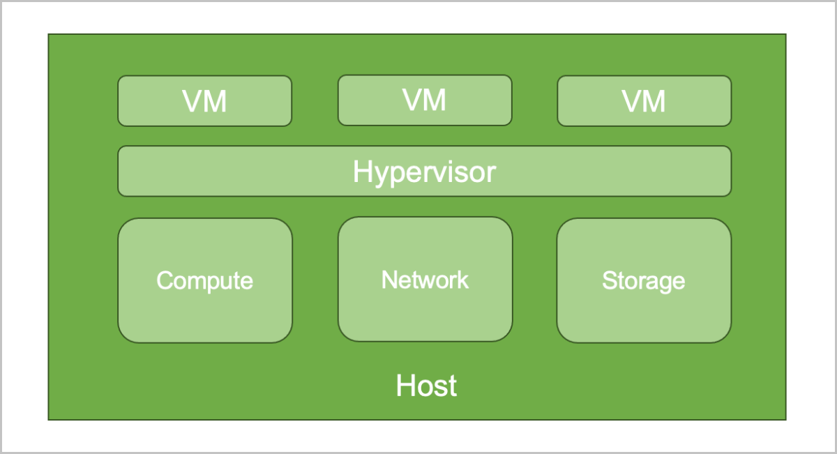
What is Host?
A host provides compute, network, and storage resources for VM instances. Hosts are core resources on the Cloud. VM instances are running on hosts.
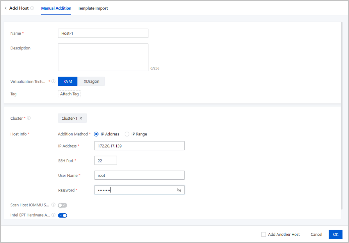
Add a Host
On the main menu of ZStack Cloud, choose . On the Host page, click Add Host. Then, the Add Host page is displayed.
- Manual addition
- Import template
Manual Addition
- Name: Enter a name for the host.
The name must be 1 to 128 characters in length and can contain Chinese characters, letters, digits, spaces, hyphens (-), underscores (_), periods (.), parenthesis (), colons (:), and plus signs (+) and cannot begin or end with spaces.
- Description: Optional. Enter a description for the host.
- Virtualization Technology: Select the hypervisor type
of the server. You can select KVM or X-Dragon.
- If the server applies the KVM virtualization technology, select KVM.
- If the server applies the X-Dragon architecture, select X-Dragon.
- Tag: Optional. Attach one or more tags to the host.
- Cluster: Select the cluster where the host is located.Note:
- Hosts that apply the KVM virtualization technology can be added only to KVM-based clusters.
- You can enable network acceleration support for a KVM-based
cluster. If you add a host to a cluster for which network
acceleration support is enabled, note that:
- If the L2 network associated with the cluster uses the Smart NIC network acceleration mode, the host must be attached with a smart NIC of the specified model.
- Hosts of the X-Dragon architecture can be added only to X-Dragon-based clusters.
- X-Dragon-based clusters do not support network acceleration support.
- Host Info: Configure the host information such as the
host IP and SSH port according to your actual needs. You can configure the
host information by entering an IP address or an IP range.
- If you select the IP Address method, set the
following parameters:
- IP Address: Enter the IP address of the host.
- SSH Port: Enter the SSH port of the host. Default: 22.
- SSH Username: Enter the SSH user name of the host. Default: root. You can enter a user name according to your actual needs.
- SSH Password: Enter an SSH password for the user name.
- If you select the IP Range method, set the
following parameters:
- IP Range: Enter the planed IP range for the host.
- SSH Port: Enter the SSH port for the
host. Default: 22.Note: Make sure that all hosts in the
specified IP range share the same SSH port.
- SSH Username: Enter the user name of
the host. Default: root. You can enter a user name according
to your actual needs.Note: Make sure that all hosts in the
specified IP range share the same user name.
- SSH Password: Enter a password for
the user name.Note: Make sure that all user name in the
specified IP range share the same password.
- If you select the IP Address method, set the
following parameters:
- Scan Host IOMMU Setting: Optional. Choose whether to
scan the IOMMU setting of the host. The IOMMU setting is used in scenarios
such as peripheral device passthrough and virtualization. By default, the
host IOMMU setting is not scanned.Note: If you choose to scan the host IOMMU
setting, note the following:
- Scanning the host IOMMU setting will traverse available GPU devices on the host and physical NICs that can be virtualized. Before you scan the setting, make sure that Intel VT-d or AMD IOMMU is enabled in the host BIOS.
- Before you can use GPU passthrough, vGPU virtualization, and SR-IOV, scan the host IOMMU setting.
- If you are scanning the host IOMMU setting for the first time, restart the host to make the setting take effect.
- Intel EPT Hardware Assist: Optional. Choose whether
to enable Intel EPT hardware assist for Intel CPUs to improve the CPU
performance. By default, Intel EPT hardware assist is enabled.Note:
- If the CPU model of your Intel server is too old, you might fail to create VM instances or cannot open the console properly of the newly created VM instances. In this case, disable the Intel EPT hardware assist feature.
- Disabling Intel EPT Hardware Assist will lower the VM performance.
Import Template
- Download the configuration template.
Click Download Template to download the configuration template file in CSV format.
图 2. Configuration Template File 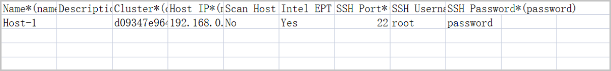
- Fill in the host information according to the specified format.
The configuration template contains a header and a row of sample. You can delete or overwrite the sample as needed.
Set the following parameters in the template:- Name: Enter a name for the host. If null, the Cloud allocates a name (HOST-host IP address) to the host by default.
- Description: Optional. Enter a description for the host.
- Cluster: Enter the UUID of the cluster
where the host is located.Note: You can add only KVM-based
clusters in the template.
- Host IP: Enter an IP address or an IP
range for the host.
- IP Address: Enter the specified IP address of the host.
- IP Range: Enter the specified IP range to bulk add hosts.Note:
If you enter multiple IP ranges for the host, use commas (,) to separate the ranges. ^ means that the IP range is not included. For example,
192.168.0.1-192.168.0.100,^192.168.0.3-192.168.0.5
- Scan Host IOMMU Setting: Optional. Choose
whether to scan the IOMMU setting of the host. The IOMMU setting
is used in scenarios such as peripheral device passthrough and
virtualization. By default, the host IOMMU setting is not
scanned.Note: If you choose to scan the host IOMMU setting,
note the following:
- To enable this feature, enter YES, Yes, yes, Y, or y. To disable this feature, enter NO, No, no, N, or n. If null, this feature is disabled.
- Before you can use GPU passthrough, vGPU virtualization, and SR-IOV, scan the host IOMMU setting.
- Scanning the host IOMMU setting will traverse available GPU devices on the host and physical NICs that can be virtualized. Before you scan the setting, make sure that Intel VT-d or AMD IOMMU is enabled in the host BIOS.
- If you are scanning the host IOMMU setting for the first time, restart the host to make the setting take effect.
- Intel EPT Hardware Assist: Optional.
Specify whether to enable Intel EPT hardware assist for Intel
CPUs to improve the CPU performance.Note: When you set this
parameter, note the following:
- If you enter YES, Yes, yes, Y, or y, the Intel EPT hardware assist will be enabled. If you enter NO, No, no, N, or n, the Intel EPT hardware assist will be disabled. If null, this feature is disabled.
- If the CPU model of your Intel server is too old, you might fail to create VM instances or cannot open the console properly of the newly created VM instances. In this case, disable the Intel EPT hardware assist feature.
- Disabling Intel EPT Hardware Assist will lower the VM performance.
- SSH Port: Enter the SSH port for the host. If null, the Cloud will use port 22 by default.
- SSH User Name: Enter the SSH user name of the host.
- SSH Password: Enter an SSH password for the user name.
- Upload the configuration file.
After you fill in the host information, verify that the grammar is correct, and then upload the file to the Cloud.
图 3. Import Template 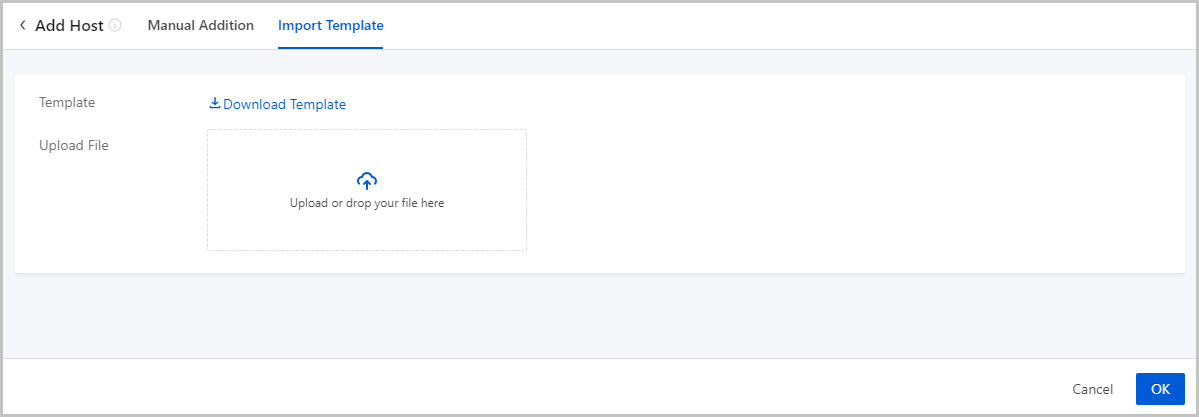
- Add hosts by using the template.
Click OK. Then, the Cloud add hosts according to the configuration file.
Manage a Host
On the main menu of ZStack Cloud, choose . Then, the Host page appears.
| Action | Description | Preconditioned Host Status |
|---|---|---|
| Add Host | Add one or more hosts. | / |
| Edit Host | Edit the name and description of a host. | / |
| Enable Host | Enable a host. | Disabled |
| Disable Host | Disable a host.Note: Disabling a host does not
affect the resources already running on the host. However, the
host is no longer available as a candidate when you apply for
new resources. |
Enabled |
| Reconnect Host | Reconnect a host.Note: In most cases, host
reconnection can be implemented when the host configurations are
updated. For example, if the memory or volume capacity of a hots
is updated, you can reconnect the host to update the
database. |
ALL |
| Enter Maintenance Mode | Enter the maintenance mode. If a host is in
maintenance mode, you can power off the host or troubleshoot
failures.
Note: If the primary storage is of a shared storage type, you can configure
the policy on failures of VM migration triggered when the host
enters maintenance mode.On the main menu of ZStack Cloud, choose , and configure the Policy for VM Migration
Failure in Entering Host Maintenance Mode
setting:
|
Connected |
| Add Bond | Aggregates the physical NIC ports on the host, so
as to realize a high availability or a load balance. Supports two
bond mode: active-backup and LACP.
Note: Make sure that the NIC ports added to a same bond have a
same speed rate. |
ALL |
| Power on | Power on a host. | Powered off |
| Power off | Power off a host.Note:
|
Powered on/Unknown |
| Restart | Restart a host.Note:
|
Powered on/Unknown |
| Enter Web Terminal | Enter a web terminal of a host to perform operations on the host. | Powered on/Unknown |
| Attach Tag | Attach a tag to one or more hosts.Note:
|
ALL |
| Detach Tag | Detach a tag from a host.Note:
|
ALL |
| Modify IPMI Info | Modify the IPMI username and password of the
host.Note: You can only modify the IPMI info of a host that is
in IPMI Unmanaged or Unknown power status. |
Unknown |
| Update SSH Password | Update the SSH password of a host. After the password is updated, the host is automatically reconnected. | / |
| Delete Host | Delete a host.Note: If you delete a host, note
that:
|
/ |
Host Details
pNUMA Topology
pNUMA Topology: A pNUMA topology (physical NUMA topology) is the topology of the host NUMA nodes predefined by the CPU vendor based on the host NUMA architecture.
Concepts
- NUMA: Non-uniform memory access (NUMA) is a computer memory design where the memory access time depends on the memory location relative to the CPU. Under NUMA, a processor can access its own local memory faster than non-local memory and thus improves VM performance.
- pNUMA node: A pNUMA node (physical NUMA node) is a host NUMA node predefined based on the host NUMA architecture. It is used to manage the CPUs and memory of the host. A pNUMA node mainly consists of pCPUs and local memory.
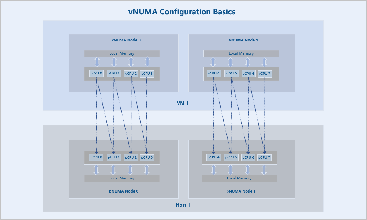
- vNUMA node: A vNUMA node (virtual NUMA node) is generated by passing-through associated pNUMA nodes via CPU pinning. It is used to manage the CPUs and memory of a VM instance. A vNUMA node mainly consists of vCPUs and local memory.
- vNUMA topology: A vNUMA topology (virtual NUMA topology) is the topology of VM NUMA nodes generated by passing-through associated pNUMA nodes via CPU pinning.
- Local memory: Local memory is the memory that a CPU (pCPU or vCPU) accesses through the Uncore iMC (Integrated Memory Controller) of the same NUMA (pNUMA or vNUMA) node. Compared with accessing non-local memory, accessing local memory has lower latencies.
Fundamentals
After you add a host on ZStack Cloud, you can view the pNUMA topology of the host. You can also configure vNUMA for VM instances running on the host according to the pNUMA topology.
vNUMA configurations are achieved through CPU pinning, which assigns the vCPUs of a VM instance to specific pCPUs of the host. In vNUMA configurations, all vCPUs of the VM instance are pinned to pCPUs of the host. In addition, the pCPUs pinned by a vCPU belong to the same pNUMA node.
After the vNUMA configurations are completed, a vNUMA topology with one or more vNUMA nodes is generated by passing-through the topology of associated host pNUMA nodes. Then the vCPUs of the VM instance primarily access the local memory of the vNUMA node where the vCPUs reside.
pNUMA Topology
- All pNUMA nodes of the host and the VM instances associated with each pNUMA node are displayed.
- Total Memory: The total amount of local memory that a pCPU can access from the pNUMA node where it resides.
- Free Memory: The amount of free local memory that a pCPU can access from the pNUMA node where it resides.
- Both the total memory and free memory are measured based on physical hardware resources.
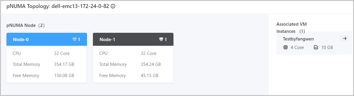
You can click the Redirect icon to view the vNUMA topologies of the associated VM instances. For more information about vNUMA topologies, see vNUMA Topology.
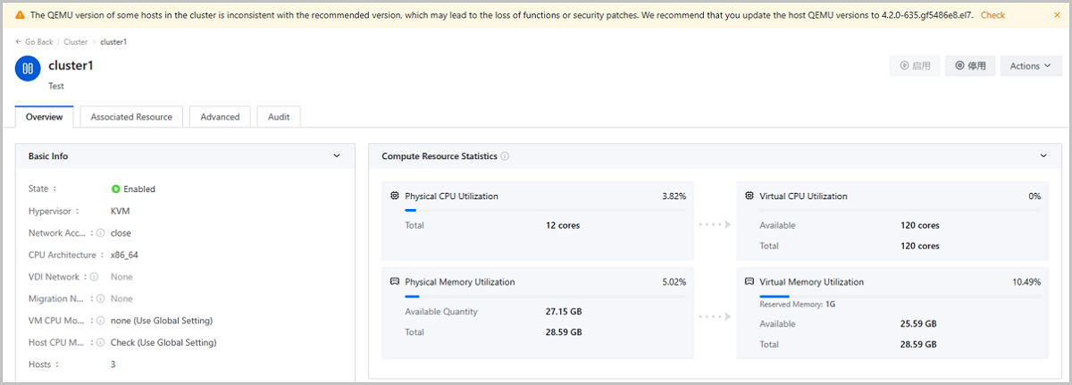
Host QEMU Version
Version Requirement
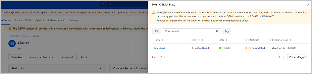
- All hosts in a same cluster should be installed with QEMU of the same version. If you need to add a host with a QEMU version different from those of other hosts in the cluster, update the QEMU of the hosts in this cluster to the Cloud recommended version or create a new cluster to add this new host.
- To avoid function or security patch losses, we recommend that all hosts use QEMU of the recommended version.
View Host QEMU Version
Update Host QEMU Version
ZStack Cloud allows you to update the QEMU version for all hosts in a cluster. Note that the QEMU update is a risky action. Before you execute the QEMU update, contact our technical support to evaluate the risk level.
- Check the connection of Cloud services and hardware.
- Set VM HA mode as None in Global Setting.
- Query the host QEMU version.
- Back up the database of the two management nodes.
- Upload the latest ISO image to the two management nodes and update the local repo source.
- Use CLI commands to updates QEMU version for hosts in the cluster.
- Use CLI commands to query the update process and confirm that the update is successful.
Note: For detailed update commands, contact our technical supports.Considerations
- After the update, restart or migrate the VM instances, VPC vRouters, and LB instances on the hosts to make the update take effect.
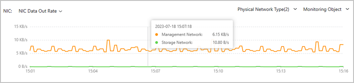
- When the QEMU version of a VM instance, VPC vRouter, or LB instance is not
consistent with that of the host it resides on, its QEMU state is displayed
as To be Updated. You can restart or migrate the VM/VPC vRouter/LB Instance
to update its QEMU version.
图 2. VM Instance QEMU State 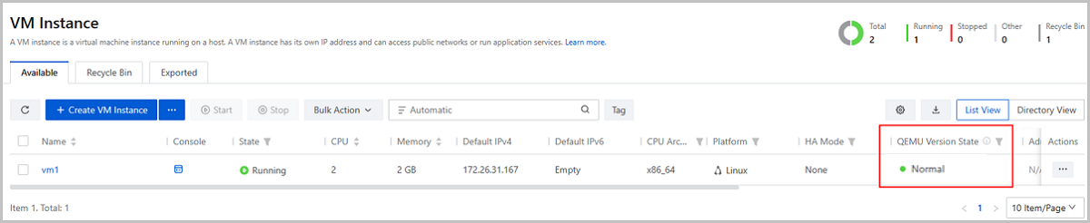
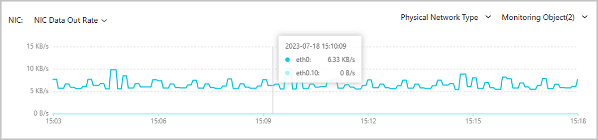
图 3. VPC vRouter QEMU State 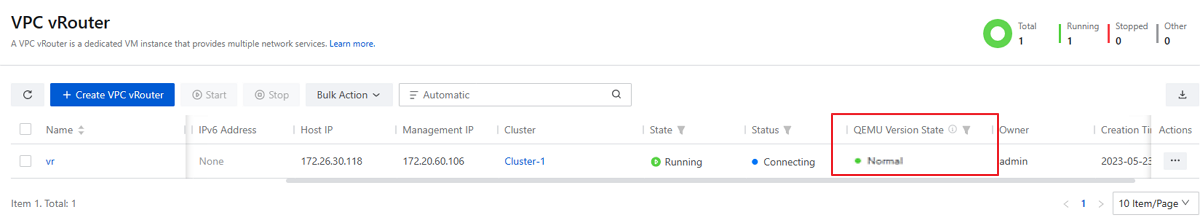
图 4. LB Instance QEMU State 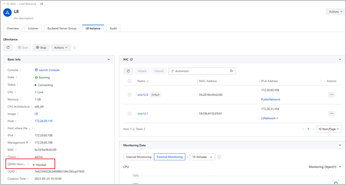
Host Hardware Monitoring
On the main menu of ZStack Cloud, choose . Then, the Host page is displayed. Click the host name and enter the host details page.
On the host details page, you can view the host hardware info and hardware status.
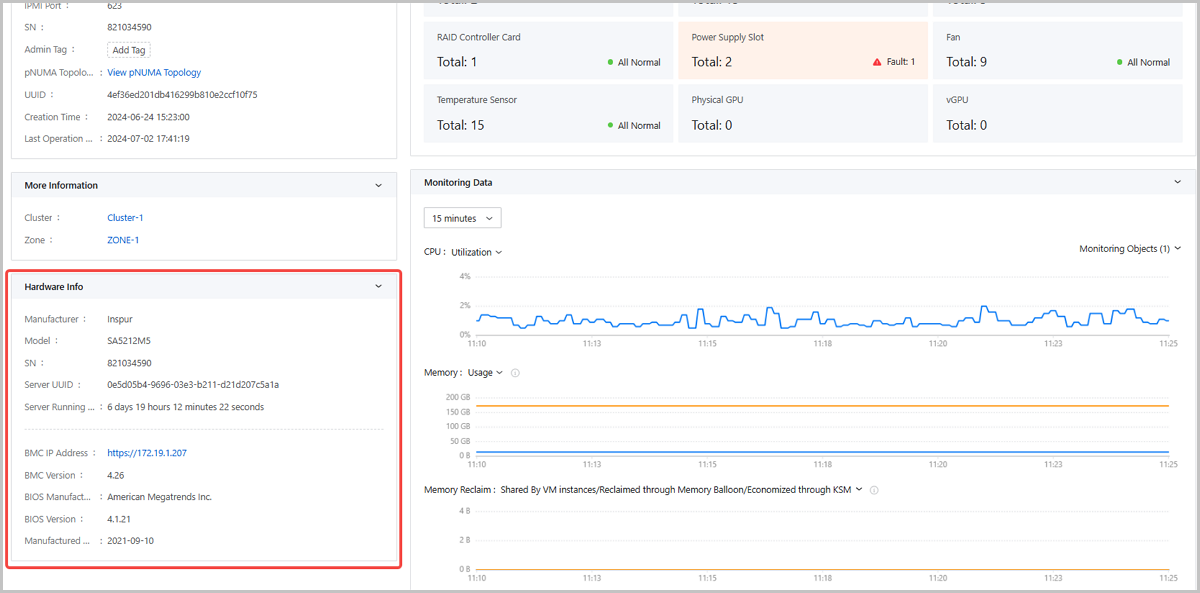
Hardware Info
On the lower left corner of the host details page, you can view a Hardware Info card, displaying the physical server manufacture, model, SN, server UUID, server running time, BMC IP address, BMC version, BIOS manufacture, BIOS version, and manufactured date.
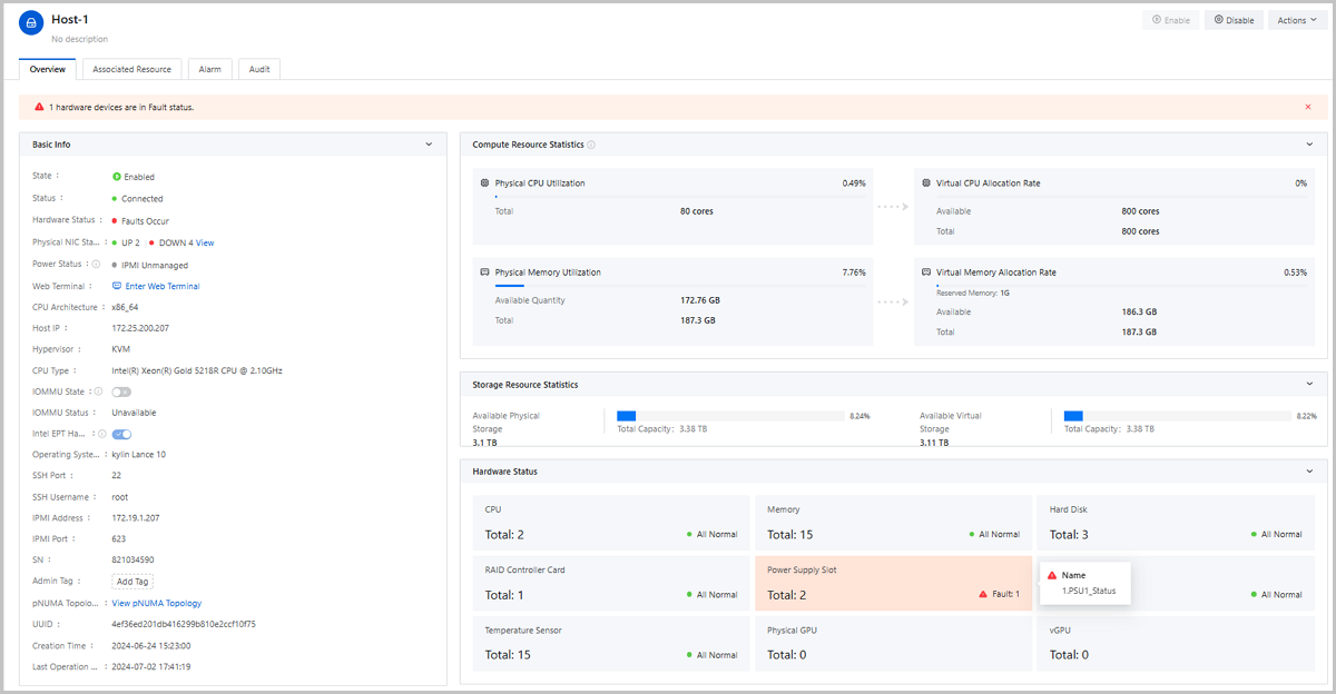
Hardware Status
- CPU: Displays the total CPU count and faulty CPU count (if any). Click the card, you can view the faulty CPU's series numbers.
- Memory: Displays the total memory count and faulty memory count (if any). Click the card, you can view the faulty memory slots.
- Disk: Displays the total disk count and faulty disk count (if any). Click the card, you can view the faulty disk slots.
- RAID Card: Displays the total RAID card count and faulty RAID card count (if any). Click the card, you can view the faulty RAID card target IDs.
- Power Supply Slot: Displays the total power supply slot count and faulty power supply slot count (if any). Click the card, you can view the faulty power supply slot names.
- Fan: Displays the total fan count and faulty fan count (if any). Click the card, you can view the faulty fan names.
- Temperature Sensor: Displays the total temperature sensor count and faulty temperature sensor count (if any). Click the card, you can view the faulty temperature sensor names.
- Physical GPU: Displays the total pGPU count and faulty pGPU count (if any). Click the card, you can view the faulty pGPU slots.
- vGPU: Displays the total vGPU count and faulty vGPU count (if any). Click the card, you can view the faulty vGPU names.
If a hardware fault occurs, you can view alert at the top of the host details page.
Primary Storage
What is Primary Storage?
A primary storage is one or more servers that store volume files of VM instances. These files include root volume snapshots, data volume snapshots, image caches, root volumes, and data volumes.
- Local Storage: This type of primary storage uses the hard disks to store disk files.
- Network Shared Storage: This type of primary storage supports NFS, Shared
Mount Point (SMP), Ceph, SharedBlock, Vhost, CBD, AliyunNAS, and
AliyunEBS.
- NFS primary storage uses the Network File System (NFS) to store files.
- SMP primary storage supports network shared storage provided by commonly used distributed file systems, such as MooseFS, GlusterFS, OCFS2, and GFS2.
- Ceph primary storage uses distributed block storage to store files.
- SharedBlock primary storage uses shared block storage to store files.
- Vhost primary storage uses vhost-user mode to connect with high-performance SSD distributed storage.
- CBD connects high-performance distributed block storage through the CBD interface.
- AliyunNAS primary storage uses distributed files to store files.
- AliyunEBS primary storage uses distributed block storage to store files.
| Primary Storage | Cluster |
|---|---|
| LocalStorage | A cluster can have one or more LocalStorage primary storage attached. |
| NFS | A cluster can have one or more NFS primary storage attached. |
| SharedBlock | A cluster can have one or more SharedBlock primary storage attached. |
| SMP | A cluster can have one SMP primary storage attached. |
| Ceph | A cluster can have only one Ceph primary storage attached. |
| Vhost | A cluster can have only one Vhost primary storage attached. |
| CBD | A cluster can have only one CBD primary storage attached. |
| AliyunNAS | A cluster can have only one AliyunNAS primary storage attached. |
| AliyunEBS | A cluster can have only one AliyunEBS primary storage attached. |
| LocalStorage + NFS | A cluster can have one LocalStorage and one NFS primary storage attached. |
| LocalStorage + SMP | A cluster can have one LocalStorage and one SMP primary storage attached. |
| LocalStorage + SharedBlock | A cluster can have multiple LocalStorage and multiple SharedBlock primary storage attached. |
| Ceph + LocalStorage | A cluster can have both a Ceph and a maximum of three LocalStorage primary storage attached. |
| Ceph + SharedBlock |
|
| Ceph + NFS | A cluster can have both a Ceph and multiple NFS primary storage attached. |
| NFS + SharedBlock | A cluster can have both multiple NFS and multiple SharedBlock primary storage attached. |
| CBD + Shared Block |
A cluster can have both a CBD and multiple SharedBlock primary storage attached. |
| CBD + Local Storage |
A cluster can have both a CBD and multiple Local Storage primary storage attached. |
| CBD + Ceph |
A cluster can have both a CBD and a Ceph primary storage attached. |
| Vhost + Shared Block |
A cluster can have both a Vhost and multiple SharedBlock primary storage attached. |
Add a Primary Storage
On the main menu of ZStack Cloud, choose . On the Primary Storage page, click Add Primary Storage. Then, the Add Primary Storage page is displayed.
- Add a LocalStorage primary storage.
- Add an NFS primary storage.
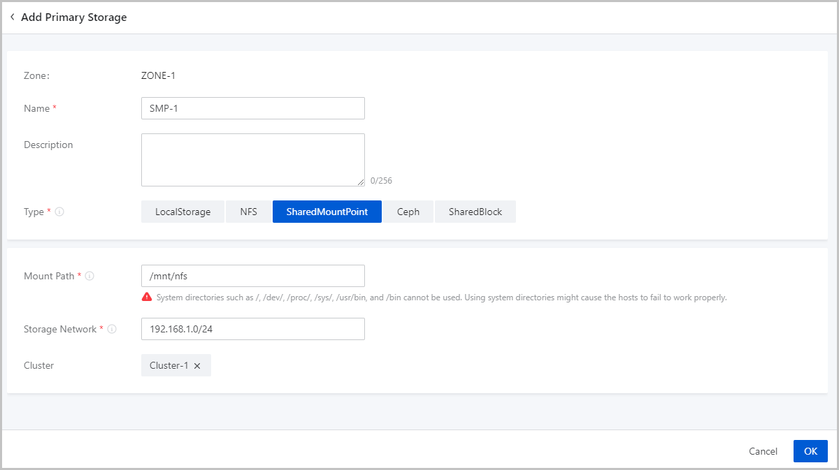
- Add a SharedMountPoint (SMP) primary storage.
- Add a Ceph primary storage.
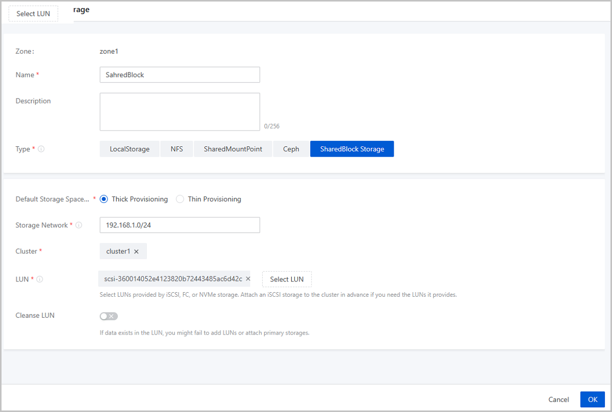
- Add a SharedBlock primary storage.
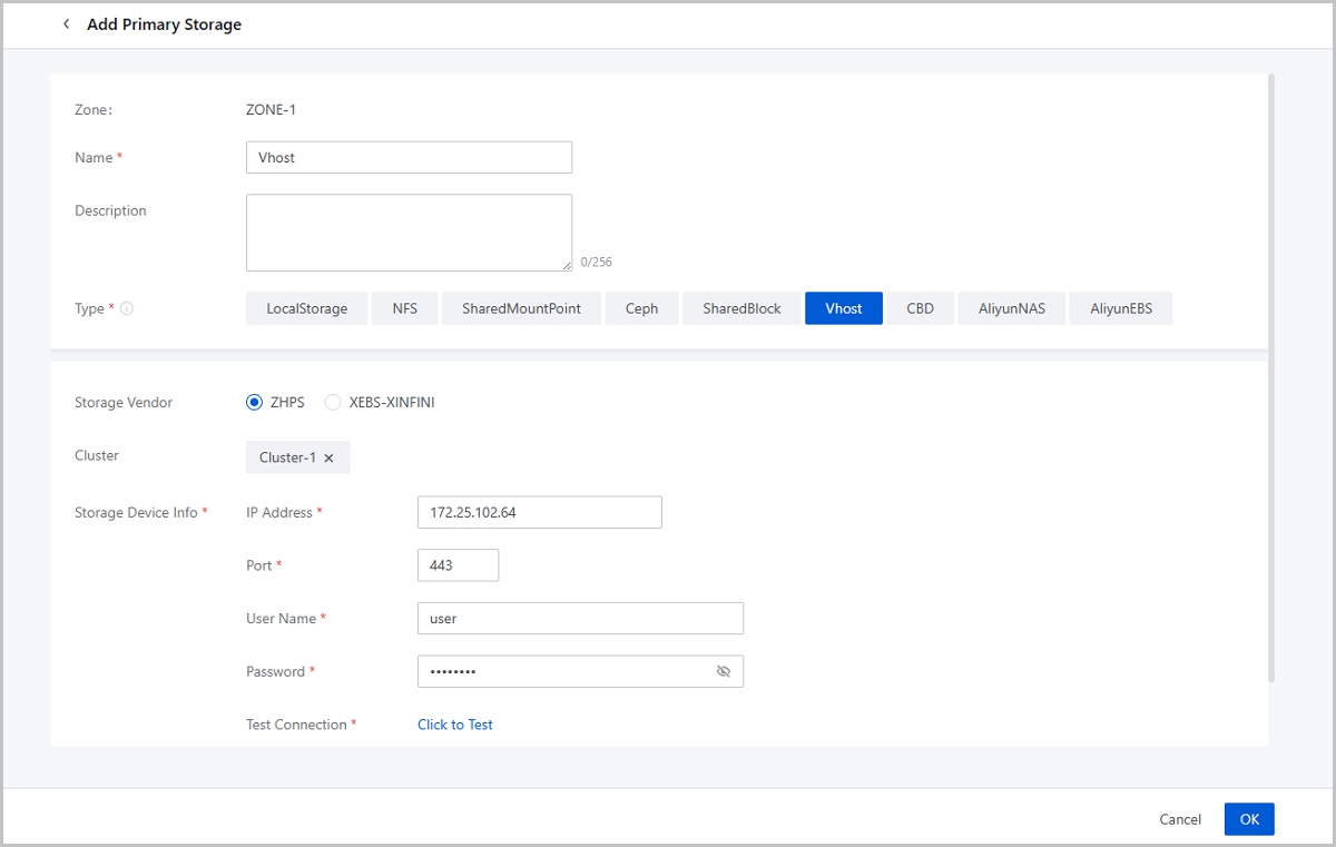
- Add a Vhost primary storage.
- Add a CBD primary storage.
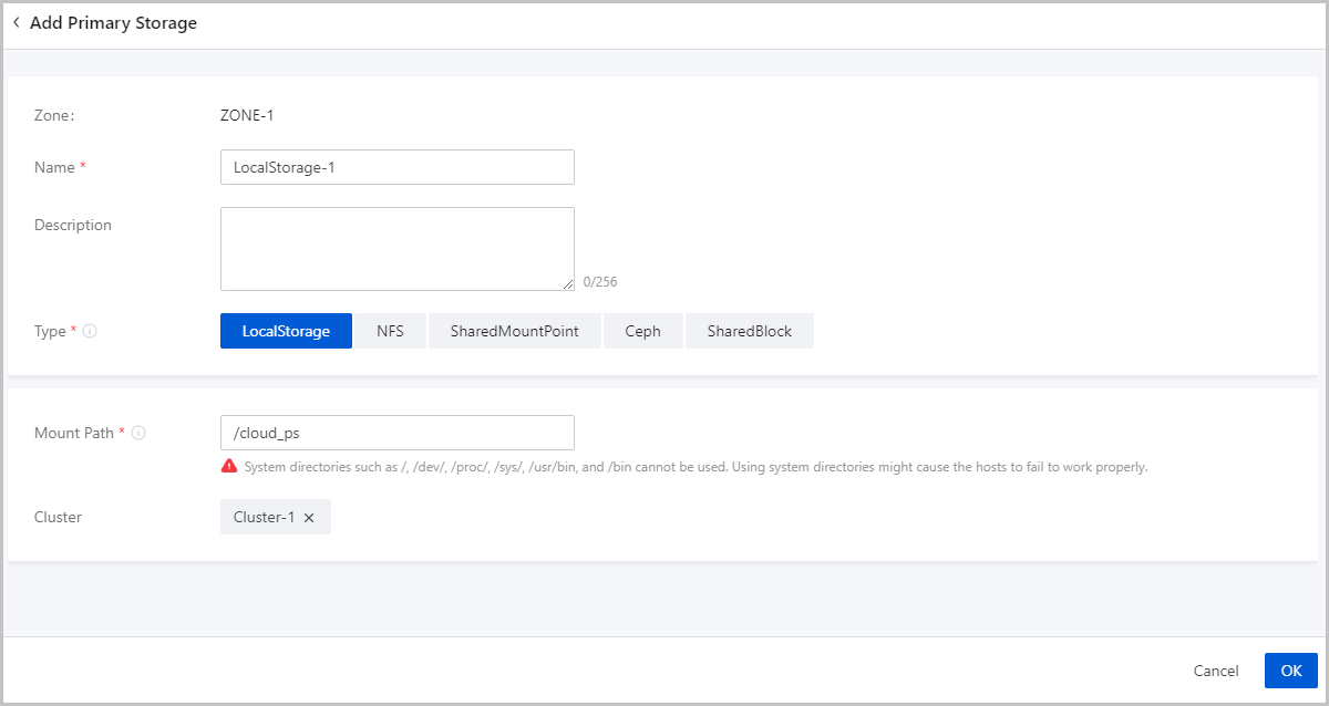
Add a LocalStorage Primary Storage
- Zone: By default, the current zone is displayed.
- Name: Enter a name for the primary storage.
The name must be 1 to 128 characters in length and can contain Chinese characters, letters, digits, spaces, hyphens (-), underscores (_), periods (.), parenthesis (), colons (:), and plus signs (+) and cannot begin or end with spaces.
- Description: Optional. Enter a description for the primary storage.
- Type: Select LocalStorage.Note:
- If you select LocalStorage, the Cloud uses the hard disks of each host as a primary storage. LocalStorage primary storage can work with ImageStore and SFTP image storage. The total capacity of a LocalStorage primary storage is the sum of each host directory capacity.
- If you attach multiple LocalStorage primary storage, make sure that each LocalStorage primary storage is deployed on an exclusive logical volume or physical disk.
- Mount Path: Enter the directory for mounting the
LocalStorage primary storage.Note:
- If the directory you entered does not exist, the Cloud automatically creates one.
- The following system directories cannot be used. Otherwise, the
hosts might fail to work properly.
- /
- /dev
- /proc
- /sys
- /usr/bin
- /bin
- Cluster: Select a cluster to which the LocalStorage primary storage is attached.
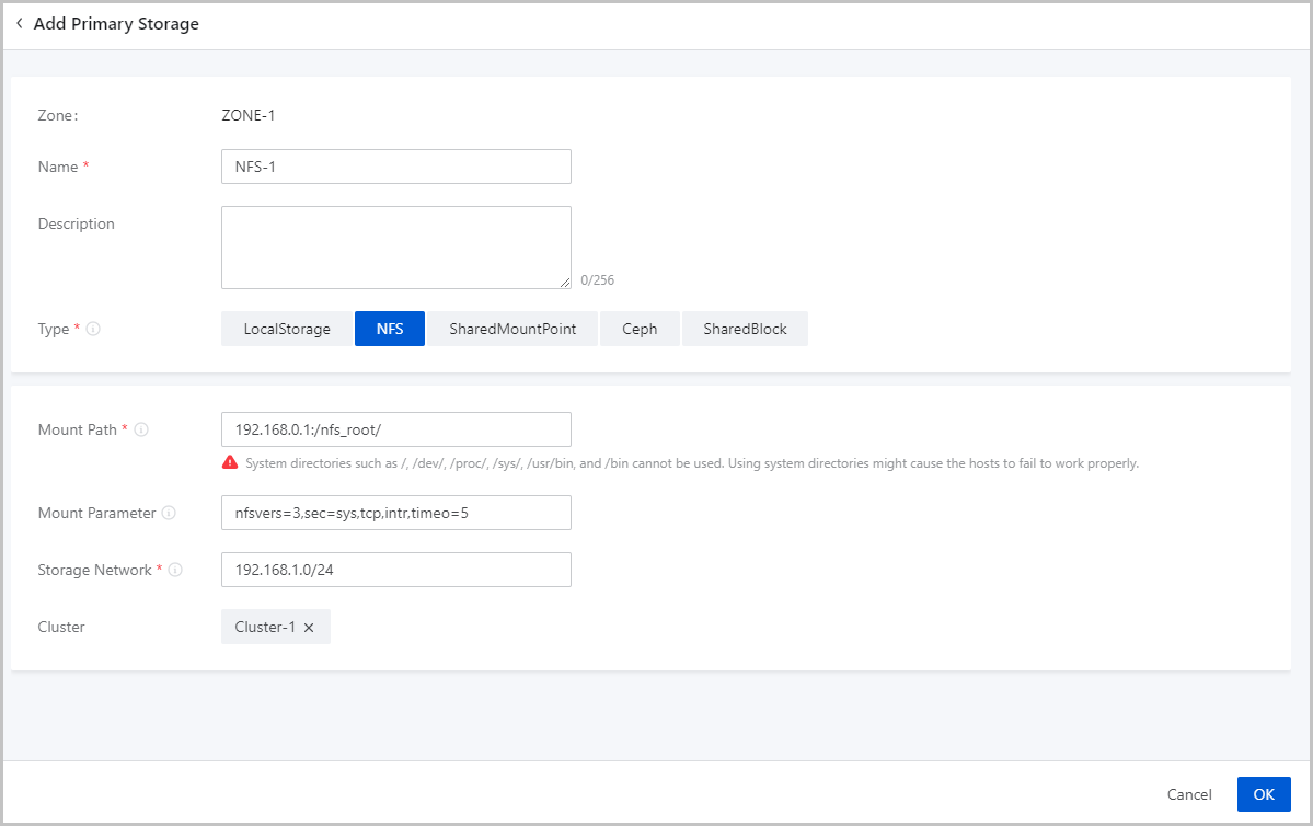
Add an NFS Primary Storage
- Zone: By default, the current zone is displayed.
- Name: Enter a name for the primary storage.
The name must be 1 to 128 characters in length and can contain Chinese characters, letters, digits, spaces, hyphens (-), underscores (_), periods (.), parenthesis (), colons (:), and plus signs (+) and cannot begin or end with spaces.
- Description: Optional. Enter a description for the primary storage.
- Type: Select NFS.Note: If you
select NFS, ZStack Cloud automatically mounts the
same NFS shared directory on all hosts as a primary storage. NFS primary
storage can work with ImageStore and SFTP
image storage, and can automatically mount the directory on all
hosts.
- Mount Path: Enter the shared directory of the NFS server.Note:
- Format: NFS_Server_IP:/NFS_Share_folder. For example, 192.168.0.1:/nfs_root.
- You need to set the access permissions of the corresponding directories on the NFS server in advance.
- To ensure security control on the NFS server, we recommend that you configure corresponding security rules for access control.
- You can check the shared directory of the NFS server by using
the
showmount -ecommand on NFS server in advance. - The following system directories cannot be used. Otherwise, the
hosts might fail to work properly.
- /
- /dev
- /proc
- /sys
- /usr/bin
- /bin
- Mount Option: Optional. To add mount options, make
sure that these options are supported by the NFS server.Note:
- The options are separated by commas (,). For example, nfsvers=3,sec=sys,tcp,intr,timeo=5. The preceding example means that the NFS server version is 3, the standard UNIX authentication mechanism is used, TCP is used as the transmission protocol, an NFS call can be interrupted in case of an exception, and the timeout is 0.5 seconds (5/10).
- To specify the mount options, you can refer to the content in the -o option of mount.
- You can set the options according to the mount command on commonly used clients. If the configured options conflict with the NFS server, the server shall prevail.
- Storage Network: Enter the storage network specified
for the shared storage. The storage network can be the management network of
the management node.Note:
- If you have a dedicated storage network, enter its CIDR.
- We recommend that you plan an independent storage network in advance to avoid potential risks. If you do not have an independent storage network, enter the network address according to your actual needs.
- The Cloud uses the storage network to check the health status of VM instances.
- Cluster: Select a cluster to which the NFS primary storage is attached.
Add a SMP Primary Storage
Before you add a SMP primary storage, configure the corresponding distributed file system in advance, and mount the shared file system to the same file path on each host according to the client configuration of different storage systems.
- Download and install the client tool mfsmount of MooseFS, and create a directory as the mount node.
- Assuming that the IP address of the MooseFS Master Server is
172.20.12.19, create /mnt/mfs as the mount
point, and use the
mfsmountcommand to mount the MooseFS system. - You can also use the
mfssetgoalcommand to set the number of file copies to be saved as needed.
[root@localhost ~]#mkdir /mnt/mfs
[root@localhost ~]#mfsmount /mnt/mfs -H 172.20.12.19
[root@localhost ~]#mkdir /mnt/mfs/zstack
[root@localhost ~]#mfssetgoal -r 2 /mnt/mfs/zstack/
#The preceding commands mount the files in the /mnt/mfs/zstack/ directory to 172.20.12.19, and save two copies to the MooseFS storage server.- Zone: By default, the current zone is displayed.
- Name: Enter a name for the primary storage.
The name must be 1 to 128 characters in length and can contain Chinese characters, letters, digits, spaces, hyphens (-), underscores (_), periods (.), parenthesis (), colons (:), and plus signs (+) and cannot begin or end with spaces.
- Description: Optional. Enter a description for the primary storage.
- Type: Select SharedMountPoint.Note:
- For SMP primary storage, ZStack Cloud supports network shared storage provided by commonly used distributed file systems such as MooseFS, GlusterFS, OCFS2, and GFS2.
- SMP primary storage can work with ImageStore and SFTP image storage.
- Mount Path: Enter the directory of the shared storage
mounted by the host.Note:
- The following system directories cannot be used. Otherwise, the
hosts might fail to work properly.
- /
- /dev
- /proc
- /sys
- /usr/bin
- /bin
- The following system directories cannot be used. Otherwise, the
hosts might fail to work properly.
- Storage Network: Enter the storage network specified
for the shared storage. The storage network can be the management network of
the management node.Note:
- If you have a dedicated storage network, enter its CIDR.
- We recommend that you plan an independent storage network in advance to avoid potential risks. If you do not have an independent storage network, enter the network address according to your actual needs.
- The Cloud uses the storage network to check the health status of VM instances.
- Cluster: Select a cluster to which the SMP primary storage is attached.
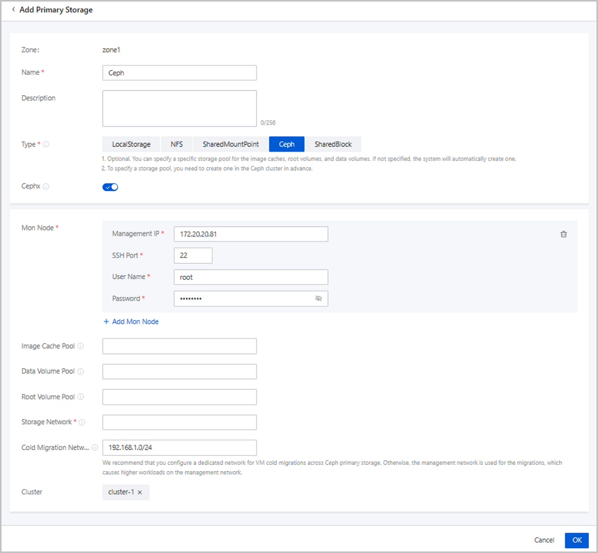
Add a Ceph Primary Storage
ZStack Cloud supports Ceph block storage. To add a Ceph primary storage, you need to add a Ceph or an ImageStore image storage, and configure the Ceph distributed storage in advance.
- Zone: By default, the current zone is displayed.
- Name: Enter a name for the primary storage.
The name must be 1 to 128 characters in length and can contain Chinese characters, letters, digits, spaces, hyphens (-), underscores (_), periods (.), parenthesis (), colons (:), and plus signs (+) and cannot begin or end with spaces.
- Description: Optional. Enter a description for the primary storage.
- Type: Select
Ceph.Note: ZStack Cloud primary storage can work with the following Ceph editions:
- Ceph open-source edition: Jewel series, Luminous series, and Nautilus series.
- ZStack Ceph Enterprise: All released ZStack Ceph Enterprise. If you are concerned more about data security and I/O performance, ZStack Ceph Enterprise is recommended. For more information, contact our official technical support.
- Cephx: Optional. Determine whether to enable Ceph authentication.Note:
- By default, Ceph authentication is enabled.
- If the network of the storage node and the compute node is relatively safe, you can disable Cephx to avoid Ceph authentication failure.
- Make sure that the key authentication of the Ceph storage is consistent with this option. If Cephx is not disabled for the Ceph storage, enabling Ceph authentication here may cause VM creation failure.
- Mon Node: Enter the IP address, SSH port, user name,
and password of the Ceph monitor.
- Management IP: Enter the IP address of the Ceph monitor.
- SSH Port: Enter the SSH port of the Ceph monitor. Default: 22.
- User Name: Enter the user name of the Ceph monitor.
- Password: Enter the password of the Ceph monitor.
You can click Add Mon Node to add more Ceph monitors.
- Image Cache Pool: Optional. Enter the name of an
image cache storage pool.Note:
- You can specify a storage pool for image caches. If you do not specify a storage pool, the Cloud creates one automatically.
- If you specify a storage pool, make sure that a storage pool is already available in the Ceph cluster. Then you can specify the UUID of a storage pool.
- Data Volume Pool: Optional. Enter the name of a data
volume storage pool. Note:
- You can specify a storage pool for data volumes. If you do not specify a storage pool, the Cloud creates one automatically.
- If you specify a storage pool, make sure that a storage pool is already available in the Ceph cluster. Then you can specify the UUID of a storage pool.
- Root Volume Pool: Optional. Enter the name of a root
volume storage pool.Note:
- You can specify a storage pool for root volumes. If you do not specify a storage pool, the Cloud creates one automatically.
- If you specify a storage pool, make sure that a storage pool is already available in the Ceph cluster. Then you can specify the UUID of a storage pool.
- Storage Network: Enter the storage network specified
for the shared storage. The storage network can be the management network of
the management node.Note:
- If you have a dedicated storage network, enter its CIDR.
- We recommend that you plan an independent storage network in advance to avoid potential risks. If you do not have an independent storage network, enter the network address according to your actual needs.
- The Cloud uses the storage network to check the health status of VM instances.
- Cold Migration Network: A network dedicated for VM
cold migrations across Ceph primary storage. If not set, the system uses the
management network for VM cold migrations across Ceph primary storage by
default.Note: To avoid high workloads on the management network, we
recommend that you set a Dedicated network for VM cold migrations and
ensures the cold migration network connectivity between Ceph primary
storage.
- Ceph Enterprise Access Token: Optional.
If you add the access token, the ZStack Ceph Enterprise
storage is managed by the token. Both elastic baremetal clusters and KVM
clusters can use the token.Note:
- Make sure that your ZStack Ceph Enterprise license is valid.
- If you need to attach Ceph block storage volumes to elastic baremetal instances, add an Access Token in advance.
- If you add an Access Token and use this Ceph primary storage to create an elastic baremetal instance (startup method: volume), the system automatically creates a block storage volume on the storage, which serves as the system volume of the instance.
- Cluster: Select a cluster to which the Ceph primary storage is attached.
Add a SharedBlock Primary Storage
- Zone: By default, the current zone is displayed.
- Name: Enter a name for the primary storage.
The name must be 1 to 128 characters in length and can contain Chinese characters, letters, digits, spaces, hyphens (-), underscores (_), periods (.), parenthesis (), colons (:), and plus signs (+) and cannot begin or end with spaces.
- Description: Optional. Enter a description for the primary storage.
- Type: Select SharedBlock.Note:
- SharedBlock primary storage uses LUN devices for storage and can work with ImageStore image storage.
- You can add LUN devices online.
- Currently, SharedBlock primary storage supports two shared access protocols: iSCSI, FC, and NVMe-oF.
- Default Storage Space Allocation Strategy: Select a
storage space allocation strategy, including thick provisioning and thin
provisioning.
- Thick Provisioning: Allocates the required storage space in advance to provide sufficient storage capacities and to ensure storage performance.
- Thin Provisioning: Allocates storage spaces as needed to achieve a higher storage utilization.
- Storage Network: Enter the storage network specified
for the shared storage. The storage network can be the management network of
the management node. You need to specify a storage network if you choose
iSCSI or FC protocol.Note:
- If you have a dedicated storage network, enter its CIDR.
- We recommend that you plan an independent storage network in advance to avoid potential risks. If you do not have an independent storage network, enter the network address according to your actual needs.
- The Cloud uses the storage network to check the health status of VM instances.
- Cluster: Select a cluster to which the SharedBlock primary storage is attached.
- LUN: Select one or more LUN devices as needed. Here
you need to enter the disk unique identifier.Note:
- LUNs are provided by iSCSI, FC, or NVMe storage. Make sure that the compute node is connected with the iSCSI, FC, or NVMe storage properly, and is added to the Cloud.
- To use LUNs provided by an iSCSI storage, attach the iSCSI storage to the cluster you select for the primary storage in advance.
- Cleanse LUN: Optional. Determine whether to cleanse
LUN devices. By default, LUN devices are not cleansed.
- If you choose to cleanse LUN devices, the residual data, such as file systems, RAID, or signatures of partition tables in the LUN devices will be forced to clean up.
- If data exists in your LUN devices, and you do not cleanse the devices, you will fail to add LUN devices or attach primary storage.
- The LUN devices to be added cannot have partitions. Otherwise, you will fail to add the devices.
Add a Vhost Primary Storage
- Zone: By default, the current zone is displayed.
- Name: Enter a name for the primary storage.
The name must be 1 to 128 characters in length and can contain Chinese characters, letters, digits, spaces, hyphens (-), underscores (_), periods (.), parenthesis (), colons (:), and plus signs (+) and cannot begin or end with spaces.
- Description: Optional. Enter a description for the primary storage.
- Type: Select Vhost.Note: Vhost
primary storage uses vhost-user mode to connect with high-performance
SSD distributed storage, and can work with ImageStore image
storage.
- Vendor: Select the vendor of the Vhost storage. Currently, ZHPS and XEBS-XINFINI are supported
- Cluster: Optional. Select a cluster to which the Vhost primary storage is attached.
- Storage Device Info: Enter storage device
information. The parameters that you need to set depend on the storage
vendor.
- If the vendor is ZHPS, set the following parameters:
- IP Address: Enter the Vhost management IP address.
- Port: Enter the port of the Vhost management IP address.
- Username: Enter the username of the Vhost management IP address.
- Password: Enter the password corresponding to the username.
- Test Connection: Test the connectivity of the IP address and obtain the storage pool information.
- Storage Pool: Specify a storage pool. Make sure that a storage pool is already available in the storage cluster.
- If the vendor is XEBS-XINFINI, set the following
parameters:
- IP Address: Enter the Vhost management IP address and port. You can add multiple IP addresses. To ensure security, we recommend that you add 2 or more addresses.
- Token: Enter the Vhost token.
- Test Connection: Test the connectivity of the IP address and obtain the storage pool information.
- Storage Pool: Specify a storage pool. Make sure that a storage pool is already available in the storage cluster.
- If the vendor is ZHPS, set the following parameters:
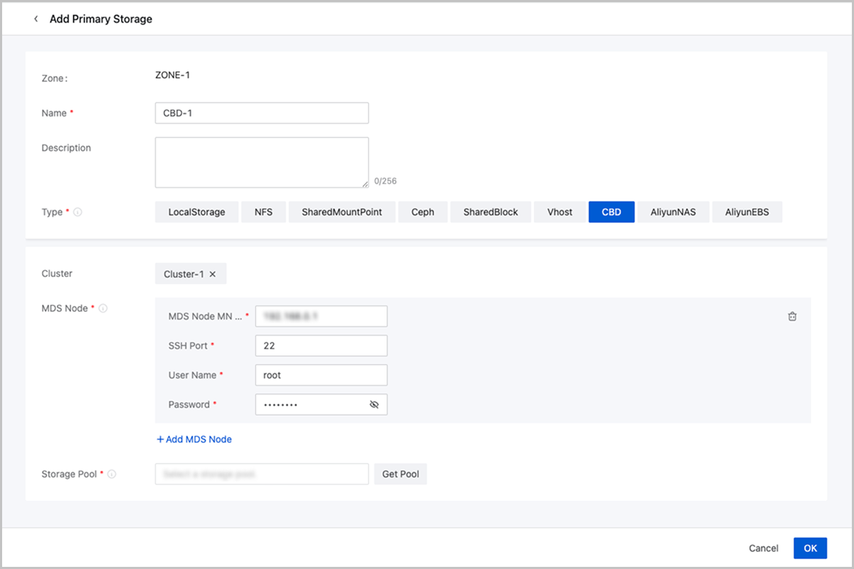
Add a CBD Primary Storage
- Zone: By default, the current zone is displayed.
- Name: Enter a name for the primary storage.
The name must be 1 to 128 characters in length and can contain Chinese characters, letters, digits, spaces, hyphens (-), underscores (_), periods (.), parenthesis (), colons (:), and plus signs (+) and cannot begin or end with spaces.
- Description: Optional. Enter a description for the primary storage.
- Type: Select CBD.
- Cluster: Select a cluster to which the primary storage is attached.
- MDS Node:
- MDS Node MN IP: Enter the management IP address of the MDS node.
- SSH Port: Enter the port of the MDS management IP address. Default: 22.
- Username: Enter the username.
- Password: Enter the password corresponding to the username.
- Storage Pool: Click Get Pool and select pools here after creating the storage pool on the storage side in advance.
Manage a Primary Storage
On the main menu of ZStack Cloud, choose . Then, the Primary Storage page is displayed.
| Action | Description |
|---|---|
| Add Primary Storage | Add a primary storage to the Cloud. |
| Edit Primary Storage | Edit the name and description of the primary storage. |
| Enable Primary Storage | Enable the disabled primary storage. |
| Disable Primary Storage | Disable the primary storage. After the primary storage is disabled, you cannot use it to create VM instances, volumes, or snapshots. However, existing resources are not affected. |
| Reconnect Primary Storage | Reconnect the primary storage. This action will
update the storage information about the primary storage.Note: If
any host can connect properly to the primary storage, the status
of the primary storage will be Connected. |
| Enter Maintenance Mode | Place the primary storage in maintenance mode.Note:
|
| Set Ceph Enterprise Access Token | Add or modify an access token for the Ceph Enterprise storage. |
| Create Volume | Create a volume on the primary storage. Then,
this volume will be an instantiated volume. Note: Shared volumes now
support only Ceph and SharedBlock primary
storage. |
| Attach Cluster | Attach the primary storage to a cluster. Note
that one cluster can have multiple primary storage attached. The following are primary storage of
the same type that a cluster can have:
The following are
combinations of primary storages that a cluster can
have:
|
| Detach Cluster | Detach the primary storage from a cluster.Note:
If you detach a primary storage from a cluster, note the
following:
If you detach a primary storage from an elastic
baremetal cluster, note the following:
|
| Delete Primary Storage | Delete the primary storage. Note: When you delete
a primary storage, note the following:
|
| Clean up Data | Clean up original data reserved during the migrations across Ceph primary storage, the migrations across NFS primary storage, and the migrations across SharedBlock primary storage. To perform this action, go to the Data Cleanup tab of the primary storage details page, and click Cleanup. These data cannot be recovered after cleanup. Please exercise caution. |
| Clean Up Storage Trash | Clean up the trash data save in the recycle bin
of a Ceph primary storage.
|
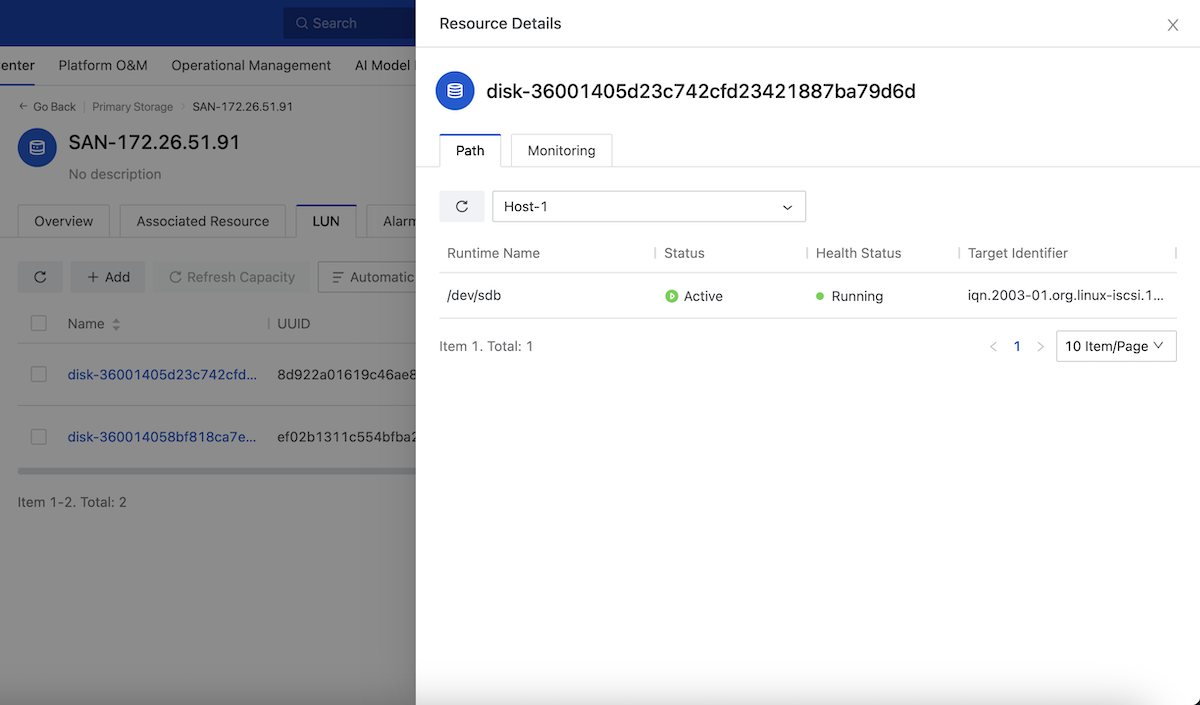
SharedBlock Details
SharedBlock LUN
On the main menu of ZStack Cloud, choose . On the Primary Storage page, click the name of a SharedBlock primary storage and enter its details page. Then, click LUN to enter the LUN tab.
View LUN Multipath
- You can specify a host to display the path information of the LUN on that host.
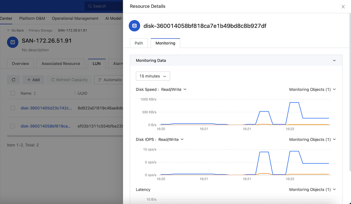
View LUN Monitoring Data
On the LUN tab, click the name of a LUN device. Then, the Resource Details page is displayed. On the Resource Details page, click Monitoring. You can view the monitoring data of the LUN on different hosts, including disk read/write, IOPS, and latency.
Vhost Details
Vhost Primary Storage Advanced Setting
| Name | Description |
|---|---|
| Primary Storage Overcommitment | The primary storage overcommitment. This parameter is used to control the size of virtual primary storage space allocated to a VM instance. Formula: Virtual primary storage available space = Total Capacity - All storage space of volumes/overcommit - All snapshot size - All image cache size - Reserved space. |
Vhost Block Storage Volume
You can divide Vhost primary storage into block storage volumes on ZStack Cloud and passthrough these block storage volumes to elastic baremetal instances to provide high-performance storage services.
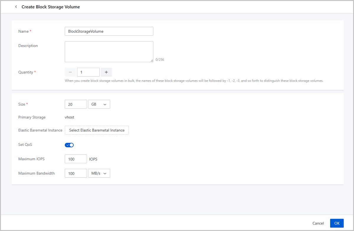
Create Block Storage Volume
On the main menu of ZStack Cloud, choose . On the Primary Storage page, click the name of a Vhost primary storage and enter its details page. On the details page, click .
- Name: Enter a name for the block storage volume. The
name must be 1~128 characters in length and can contain English letters,
digits, and the following English characters
-_. The name must start with an English letter. - Description: Optional. Enter a description for the block storage volume.
- Quantity: Set the number of block storage volumes to be created.
- Size: Set the block storage volume size. Unit: MB/GB/TB. Valid values: 1MB~1024TB. Enter an integer.
- Primary Storage: Displays the name of the current Vhost primary storage.
- Elastic Baremetal Instance: Select an elastic
baremetal instance that the block storage volume to be attached to. You can
attach the block storage volume to elastic baremetal instances during or
after the creation.Note: Attach the Vhost primary storage to the elastic
baremetal cluster before you can attach its block storage volumes to
this instance.
- Set QoS: Set QoS, including IOPS and bandwidth, for
the block storage volume.
- Maximum IOPS: The upper limit of the read/write times per second of the block storage volume. Valid values: 100~10000000. Default: Unlimited.
- Maximum Bandwidth: The upper limit of the read/write speed of the block storage volume. Unit: MB/S and GB/S. Valid values: 10MB/S~100GB/S. Default: Unlimited.
Manage Block Storage
On the main menu of ZStack Cloud, choose . On the Primary Storage page, click the name of a primary storage and enter its details page. On the details page, click and enter the Block Storage Volume page.
| Action | Description |
|---|---|
| Create Block Storage Volume | Create a block storage volume based on the Vhost primary storage. |
| Edit Block Storage Volume | Modify the name and description or a block storage volume. |
| Attach Elastic Baremetal Instance | Attach a block storage volume to an elastic
baremetal instance. A block storage volume can be attached to up
to 16 elastic baremetal instances.Note: Attach the Vhost primary
storage to the baremetal elastic cluster before you can
attach its block storage volumes to elastic baremetal
instances in it. |
| Resize Block Storage Volume | Expand the size of a block storage volume.Note:
|
| Create Block Storage Volume Snapshot | Restore the status of a block storage volume at the current time point before you exercise important operations in the block storage volume. This allows fast rollback when needed. |
| Set Block Storage Volume QoS | Set upper limits for the read/write IOPS and speed of a block storage volume. |
| Delete Block Storage Volume | Delete a block storage volume.Note: Deleting
a block storage volume also deletes all data stored on it.
Deleted data cannot be recovered. Please exercise
caution. |
CBD Details
CBD Primary Storage Advanced Setting
| Name | Description |
|---|---|
| Primary Storage Overcommitment | The primary storage overcommitment. This parameter is used to control the size of virtual primary storage space allocated to a VM instance. Formula: Virtual primary storage available space = Total Capacity - All storage space of volumes/overcommit - All snapshot size - All image cache size - Reserved space. |
Image Storage
What is Image Storage?
An image storage is a storage server that stores VM image templates, including ISO image files.
- An image storage must be attached to a zone before the resources in the zone can
access it. Note that you can share images across multiple zones by using the image storage.
图 1. Image Storage 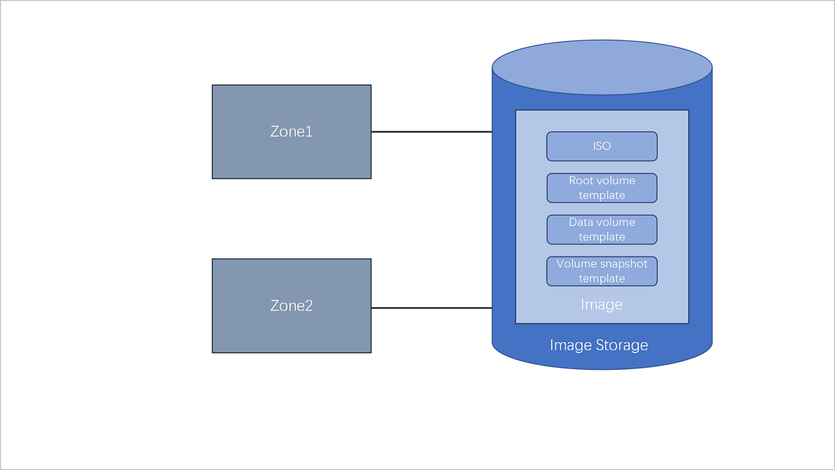
- To better manage image storage and zones, the UI specifies that one image storage can only correspond to one zone. In the UI, when you add an image storage, the image storage will be attached to the current zone by default. When you delete a zone, the image storage attached to the zone will also be deleted.
Image Storage Type
- ImageStore
- Stores image files by means of image slices and supports incremental storage.
- Allows you to create snapshots and images when VM instances are running or stopped.
- Allows you to clone VM instances without data volumes when these VM instances are running, paused, or stopped.
- Allows you to clone VM instances with data volumes when these VM instances are running, paused, or stopped, and with storage types of LocalStorage, NFS, SharedMountPoint (SMP), Ceph, or SharedBlock.
- Supports image synchronization across ImageStore image storage on the same management node.
- Allows you to obtain the existing image files under the URL path in the image storage.
- Ceph
- Stores image files by means of Ceph distributed block storage.
- Allows you to create snapshots and images when VM instances are running or stopped.
- Allows you to clone VM instances without data volumes when these VM instances are running, paused, or stopped.
- Allows you to clone VM instances with data volumes when these VM instances are running, paused, or stopped, and with the storage type of Ceph.
- Allows you to export images on the UI or image storage.
- You can export images, copy exported image URLs, and download exported images on the UI.
- You can also export images on an image storage.
For example, assume that the image path you use is ceph://bak-t-c9923f9821bf45498fdf9cdfa1749943/61ece0adc7244b0cbd12dafbc5494f0c.
Then, run the following command on the image storage:rbd export -p bak-t-c9923f9821bf45498fdf9cdfa1749943 --image 61ece0adc7244b0cbd12dafbc5494f0c --path /root/export-test.image # bak-t-c9923f9821bf45498fdf9cdfa1749943 is the name of the pool where the image resides. # 61ece0adc7244b0cbd12dafbc5494f0c is the name of the image. # /root/export-test.image is the name of the exported file.
- AliyunEBS
- Stores image by means of object storage.
- Allows you to create snapshots and images when VM instances are running or stopped.
- Allows you to clone VM instances without data volumes when these VM instances are running, paused, or stopped.
- Does not allow you to clone VM instances with data volumes.
- Allows you to export images on image storage. For more information, contact the official technical support.
Image Storage | Primary Storage
| PS/BS | ImageStore | Ceph |
| LocalStorage | ○ | × |
| NFS | ○ | × |
| SMP | ○ | × |
| Ceph | ○ | ○ |
| SharedBlock | ○ | × |
| Vhost | ○ | × |
| CBD | ○ | × |
- When primary storage are LocalStorage, NFS, or SMP, the default type for image storage is ImageStore.
- When primary storage are NFS or SMP, you can manually mount the corresponding shared directories to the local directories of the corresponding image storage. In this regard, both primary storage and image storage can use the network shared storage.
- When primary storage is Ceph, you can use the primary storage in the same Ceph cluster as image storage. You can also use the ImageStore primary storage as image storage.
- When primary storage is SharedBlock, the default type for image storage is ImageStore.
- When primary storage is AliyunNAS, the default type for image storage is ImageStore.
- When primary storage is AliyunEBS, the default type for image storage is AliyunEBS.
Add an Image Storage
On the main menu of ZStack Cloud, choose . On the Image Storage page, click Add Image Storage. Then, the Add Image Storage page is displayed.
- Add an ImageStore image storage.
- Add a Ceph image storage.
- Add an AliyunEBS image storage.
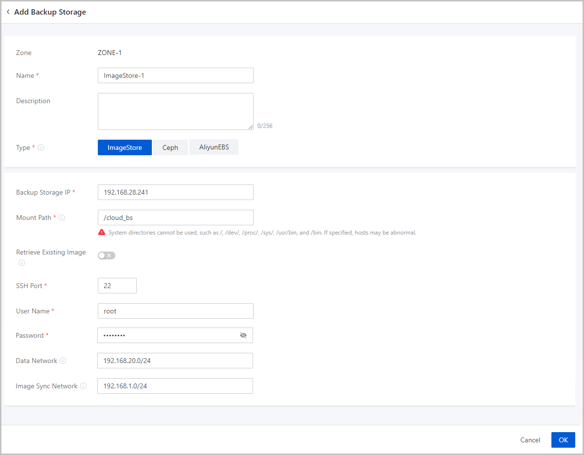
Add an ImageStore Image Storage
- Zone: By default, the current zone is displayed.
- Name: Enter a name for the image storage.
- Description: Optional. Enter a description for the image storage.
- Type: Select ImageStore.
- Image Storage IP: Enter an IP address for the ImageStore image storage.
- Mount Path: Enter the mount path of the storage to be
mounted on the ImageStore image storage. For example,
/cloud_bsNote:
- We recommend that you mount a large-capacity storage for the directory, and enter the absolute path of the directory.
- The following system directories cannot be used. Otherwise, the
hosts might fail to work properly.
- /
- /dev/
- /proc/
- /sys/
- /usr/bin
- /bin
- Retrieve Existing Image: Optional. Choose whether to
obtain existing images for the ImageStore image storage.Note:
- You can obtain existing images from the mount path of the image storage.
- Only ImageStore image storage allows you to Retrieve Existing Image.
- SSH Port: Set an SSH port for the image
storage.Note: The port must be an integer. Default: 22.
- User Name: Use either the default user name (root) or enter a user name for the image storage.
- Password: Enter the password for the user name.
- Data Network: Optional. If you planned a dedicated
network for data communication between the compute node and the image
storage, enter its CIDR.Note:
- If not set, the Cloud uses the management network by default.
- If you planned a dedicated network for data communication between the compute node and the image storage, add it directly to the Cloud.
- Image Sync Network: Optional. Enter the CIDR of the
image synchronization network.Note:
- If not set, a management network will be used by default for image synchronization.
- You can synchronize images between ImageStore image storage within the same management node.
- If you deployed a dedicated network for image synchronization, add it directly to the Cloud.
- Using a dedicated image synchronization network can avoid network congestion and improve transmission efficiencies.
- If you set an image synchronization network for both a source ImageStore and a destination ImageStore image storage, only the image synchronization network of the destination ImageStore image storage works.
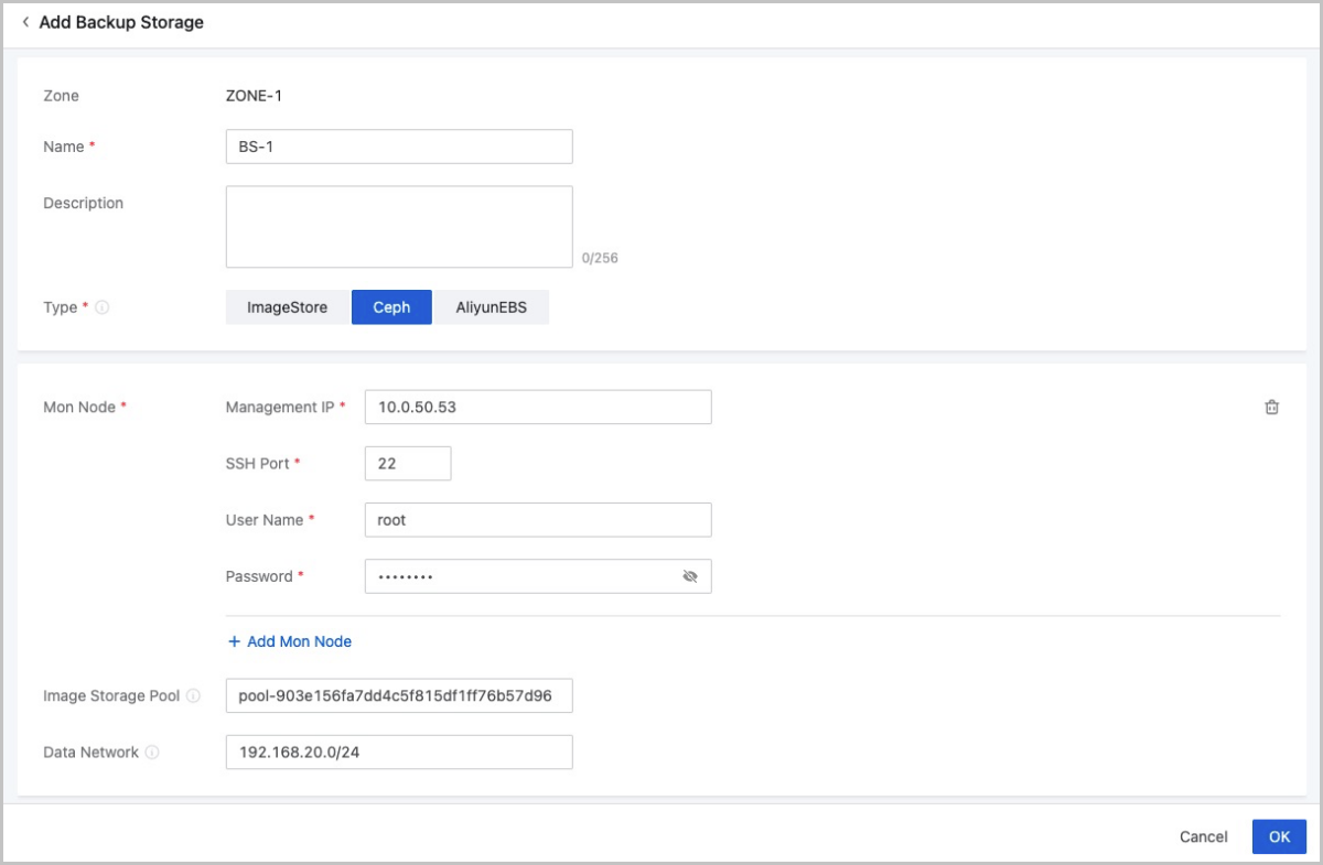
Add a Ceph Image Storage
- Zone: By default, the current zone is displayed.
- Name: Enter a name for the image storage.
- Description: Optional. Enter a description for the image storage.
- Type: Select Ceph.
- Mon Node: Configure the Ceph monitor for the Ceph
image storage, including the management IP address, SSH port, user name,
and password of the Ceph monitor.
- Management IP: Enter the IP address of the Ceph monitor.
- SSH Port: Enter the SSH port of the Ceph monitor. Default: 22.
- User Name: Enter the user name of the Ceph monitor.
- Password: Enter the password of the Ceph monitor.
Note:
- You can set the interval that the management node reconnects
the mon node of the Ceph image storage if the mon IP fails
to be detected. Method:
Go to , locate Interval of Auto-Reconnection to Monitoring Node of Image Storage, and change its values as needed. Default: 30 seconds.
- You can specify whether to enable automatic reconnection to
the mon node of the Ceph image storage if the mon IP fails
to be detected. Method:
Go to , locate Auto-Reconnection to Monitoring Node of Image Storage, and specify whether to enable it as needed. By default, the auto reconnection is enabled.
You can click Add Mon Node to add more Ceph monitors.
- Image Storage Pool: Optional. Enter an image
storage pool UUID.Note:
- You can specify a storage pool for the Ceph image storage to store images. If not specified, the Cloud creates one automatically.
- To specify a storage pool, make sure that a storage pool is already available in the Ceph cluster. Then you can specify the UUID of a storage pool.
- Data Network: Optional. Enter the CIDR of a data network.Note:
- If not set, the Cloud uses the management network by default.
- If you planned a dedicated network for data communication between the compute node and the image storage, add it directly to the Cloud.
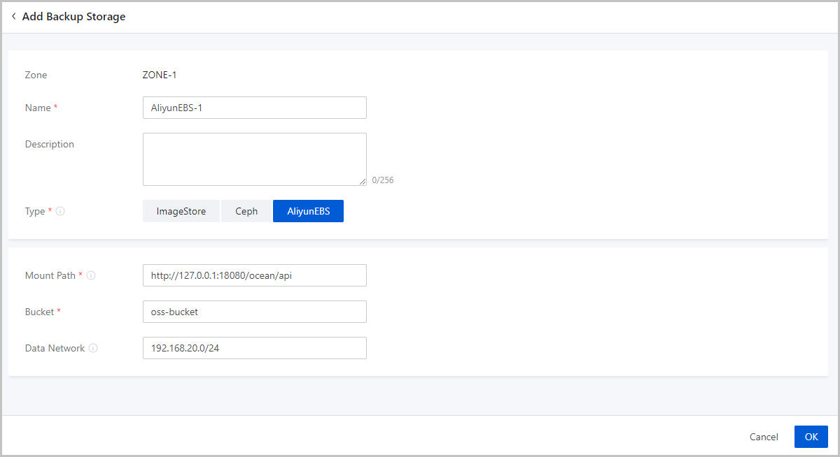
Add an AliyunEBS Image Storage
- Zone: By default, the current zone is displayed.
- Name: Enter a name for the image storage.
- Description: Optional. Enter a description for the image storage.
- Type: Select AliyunEBS.
- Mount Path: Enter an Ocean API endpoint.Note:
- AliyunEBS image storage sends requests to an Ocean server through this mount path.
- Format: http://Ocean_Server_Domain:Port/ocean/api.
- Bucket: Enter an OSS bucket you added to ZStack Cloud.Note: You can specify whether to roll
back objects in OSS buckets if an error occurs when you upload
custom images to Alibaba Cloud EBS image storage. Method:
Go to , locate Rollback Imported Image, and change its value as needed. Default: True.
- Data Network: Optional. If you planned a
dedicated network for data communication between the compute node and
the image storage, enter its CIDR.Note: If not set, the Cloud uses the
management network by default.
Manage an Image Storage
On the main menu of ZStack Cloud, choose . Then, the Image Storage page is displayed.
The following table lists the actions that you can perform on an image storage.
| Action | Description |
|---|---|
| Add Image Storage | Add an image storage to the Cloud. |
| Edit Image Storage | Edit the name and description of the image storage. |
| Enable Image Storage | Enable the disabled image storage. |
| Disable Image Storage | Disable the image storage.Note: After an image storage is
disabled, you cannot add images to this image storage. However,
you can still use existing images to create VM
instances. |
| Reconnect Image Storage | Reconnect the image storage. This action will update the storage
information about the image storage.Note:
|
| Clean up Data | Clear both the invalid data that have been completely deleted and
the temporary data that were expired on the image storage to release
storage spaces.Note:
|
| Update Password | Update the password of the image storage. You need to reconnect the image storage after the updates. |
| Delete Image Storage | Delete the image storage.Note:
|
SAN Storage
What is SAN Storage?
- iSCSI storage is an SAN storage that uses the iSCSI protocol for data transmission. You can add an iSCSI SAN block as a Shared Block primary storage or pass through the block to a VM instance.
- FC storage is an SAN storage that uses the FC technology for data transmission. You can add an FC SAN block as a Shared Block primary storage or pass through the block to a VM instance. ZStack Cloud supports FC for SAN storage connection with multi-path I/O.
Scenarios
- Passes through an iSCSI or FC disk to a VM instance.
- Adds an iSCSI or FC disk as a shared block and takes the shared block as a Shared Block primary storage.
Considerations
- You can add a disk that is not attached to a VM instance as a Shared Block primary storage.
- A logical unit number (LUN) that is added as a primary storage cannot be used for other purposes.
- You can attach a disk that is not added as a primary storage to a VM instance.
- You can attach a disk to multiple VM instances or attach multiple disks to one VM instance.
- If a block device is not attached to a VM instance and the cluster where the block device resides is in normal state, you can add the block device as a Shared Block primary storage.
- A logical unit number (LUN) that is added as a primary storage cannot be used for other purposes.
- You can attach a block device that is not added as a primary storage to a VM instance.
- You can attach a block device to multiple VM instances or attach multiple block devices to one VM instance.
Add an iSCSI Storage
On the main menu of ZStack Cloud, choose . On the iSCSI Storage page, click Add iSCSI Storage. Then, the Add iSCSI Storage page is displayed.
- Name: Enter the name of the iSCSI storage.
The name must be 1 to 128 characters in length and can contain Chinese characters, letters, digits, spaces, hyphens (-), underscores (_), periods (.), parenthesis (), colons (:), and plus signs (+) and cannot begin or end with spaces.
- IP Address: Set the IP address of the iSCSI storage.
- Port: Set the port of the iSCSI storage. Default port: 3260.
- Cluster: Optional. Select a cluster. You can also attach a cluster after you add the iSCSI storage.
- CHAP Username: Optional. Enter the CHAP username if the iSCSI storage has CHAP authentication configured.
- CHAP Password: Optional. Enter the CHAP password if the iSCSI storage has CHAP authentication configured.
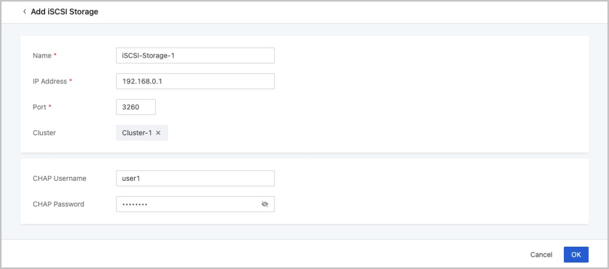
NVMe Storage
What is NVMe Storage?
NVMe Storage: A type of storage implemented via the NVMe-oF (NVMe over fabrics) protocol. You can add a block device configured from an NVMe storage as SharedBlock primary storage.
Related Concepts
- Storage device: A hardware used for storing data. Hard disk drive (HDD) and
solid state drive (SSD) are two common types of storage devices, featuring
different form factors. Common HDD and SSD form factors are listed as
follows:
- HDD form factors: 2.5 inches and 3.5 inches.
- SSD form factors: 2.5 inches, M.2, mSATA, and U.2.
- Interface: The connection that enables data transfer between storage devices
and computer software. The interface specifications of storage devices
differ from one another. Common HDD and SSD interfaces are listed as follows
in decreasing order of transfer speed:
- HDD interfaces: SAS (Serial Attached SCSI), SCSI, SATA (Serial ATA), and IDE.
- SSD interfaces: PCIe, M.2, mSATA, and SATA III.
- Protocol: The interface specification for data transfer between a physical
interface and computer software. Interfaces vary in their supported
protocols. Common protocols are listed as follows:
- AHCI (Advanced Host Controller Interface) protocol: A protocol for storage devices with SATA/M.2 interface. AHCI can be used for both HDD and SSD.
- NVMe (Non-Volatile Memory Express) protocol: A protocol for storage devices with PCIe/M.2 interface. NVMe is specifically designed for SSD.
- NVMe-oF (NVMe over Fabrics): An extension of the NVMe network protocol to
the fabric, using Ethernet, Fiber Channel, RoCE, or InfiniBand. NVMe-oF
enables all VM instances within a cluster to access NVMe storage at a high
speed, improving the overall I/O performance of a cluster.ZStack Cloud NVMe storage supports the following two types of transports:
- NVMe-oF using RDMA (NVMe-oF using Remote Direct Memory Access): This technology uses Remote Direct Memory Access (RDMA) to enable data exchange directly between two computers’ main memory. Since data exchange bypasses the processor, cache, and OS of either computer, this mechanism enables efficient data transfer with low-overhead costs. NVMe-oF using RDMA can be implemented in multiple ways, including RoCE (RDMA over Converged Ethernet), InfiniBand, and iWARP.
- NVMe over FC (NVMe-oF using FC): This specification uses Fibre Channel (FC) protocol to enable data transfer between storage arrays and VM instances within a cluster.
- NVMe of using TCP: This specification uses the standard TCP protocol to enable data transfer between storage arrays and VM instances within a cluster.
Why NVMe?
NVMe storage has the following advantages:
- Future-oriented: NVMe storage breaks the performance bottlenecks of AHCI that was specifically designed for HDDs and fully unlock the potential of SSDs. With improved performance, higher resource utilization, and reduced cost, NVMe presents an enterprise-grade storage solution that will future-proof your business.
- High performance: NVMe storage can handle queue depths of up to 65K I/O operations, each holding 65K commands. This significantly increases parallel disk IOPS along with reduced latency, greatly boosting storage performance.
Use Cases
- Electronic trading: In electronic trading, the execution price is extremely time-sensitive. In other words, a few microseconds could result in a large price difference. Therefore, low end-to-end latency is required to avoid losses due to price changes in a short time and thus maintain competitiveness.
- Real-time analytics: In the field of fraud detection, marketing applications, or games that require response time in milliseconds or even microseconds, the capability of real-time analytics could define a company’s business value. Powerful real-time analytics requires the server to respond quickly with low latency. With this capability, users can resolve potential crises, grasp business opportunities, and eventually achieve business growth.
Quick Start
- Build an NVMe backend storage.
- Log in to the Cloud and enter the NVMe Storage page where you can synchronize information of NVMe block devices.
- On the Primary Storage page, click Add Primary Storage to add a SharedBlock primary storage using LUNs provided by NVMe SSD.
- Create a VM instance with this SharedBlock primary storage.
Manage an NVMe Storage
On the main menu of ZStack Cloud, choose . Then, the NVMe Storage page is displayed.
| Action | Description |
|---|---|
| Sync Device Info | Manually refresh and then identify NVMe storage devices. |
Physical Network
What is Physical Network?
Physical Network: Real networks deployed in a physical environment, which can be divided into different categories based on their application scenarios, such as management networks, storage networks, business networks, backup networks, and migration networks. You can attach tags to a NIC port on ZStack Cloud to mark which type of network it belongs to according to your physical environment planning.
Physical Network Type
- Management Network: A network used to manage physical resources on
ZStack Cloud. The management nodes communicate
with the hosts, primary storage, image storage, VPC vRouters, and LB
instances (performance-dedicated) on the Cloud through the management
network. If you deploy a management network, it can be automatically
identified by ZStack Cloud.
- The management networks you add in comply with the management network definition here.
- The host IP addresses displayed on ZStack Cloud belong to the management network.
- The host callback IP addresses belong to the management network.
- Storage Network: A network specified for storage services. ZStack Cloud uses a storage network to get the health status of VM instances. We recommend that you deploy a dedicated storage network to avoid possible risks.
- Business Network: A network that can be added as an L2/L3 network on and attached to VM instances on ZStack Cloud. A VM instance uses a business network to provide services.
- Backup Network: A network used to back up or recover local business data in a local backup scenario. You need to deploy a backup network if you use Backup Service.
- Migration Network: A network used for VM migrations on ZStack Cloud.
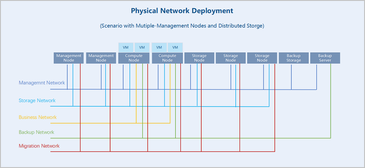
Characteristics
- The Physical Network page displays physical NIC ports (bonds and non-bonds) in fact. These NIC ports realize the network connections between hosts. You manage physical networks by managing these NIC ports.
- You can attach network-type tags to NIC ports according to your physical
environment planning. Management network tags are attached to corresponding
ports automatically by the system and other tags need to be attached by
yourself.
- If you add a management network in , the NIC port of the L2 network it belongs to is attached with a management network tag.
- The NIC port of the network to which a host IP address belongs is attached with a management network tag.
- The NIC port of the network to which a host callback IP address belongs is attached with a management network tag.
- You can add a custom network type to meet flexible needs.
- After you attach tags to corresponding NIC ports, you can view the flow monitoring of different network types, which help you master accurate network workloads more flexibly.
Manage Physical Network
On the main menu of ZStack Cloud, choose . Then, the Physical Network page is displayed.
You can make the following actions on the Physical Network page: Viewing physical NIC ports, marking NIC ports with network types, and modifying the network types of the NIC ports.
View Physical NIC Port
The Physical Network page displays all physical NIC ports (bonds and non-bonds) attached with network-type tags in the current zone. You can view such NIC port information as the NIC port name, VLAN ID, subordinated host, host IP, and network type.
Two display methods are supported: Display by Cluster and Display by Network Type.
- By Cluster: the page displays physical NIC ports in a directory tree according to the clusters and hosts they belong to. You can specify a cluster or host to screen out the physical NIC ports you need.
- By Network Type: the page displays physical NIC ports by network types they belong to. The NIC ports attached with network-type tags are displayed under corresponding categories, including management network, storage network, business network, backup network, and migration network.
Note:
- A physical NIC port can be marked as one or more network types, which means a NIC port may appear under more than one category when you choose the display method as By Network Type.
- This page does not display physical NIC ports without any network-type tags. To attach network-type tags to NIC ports, see Mark NIC Port with Network Type.
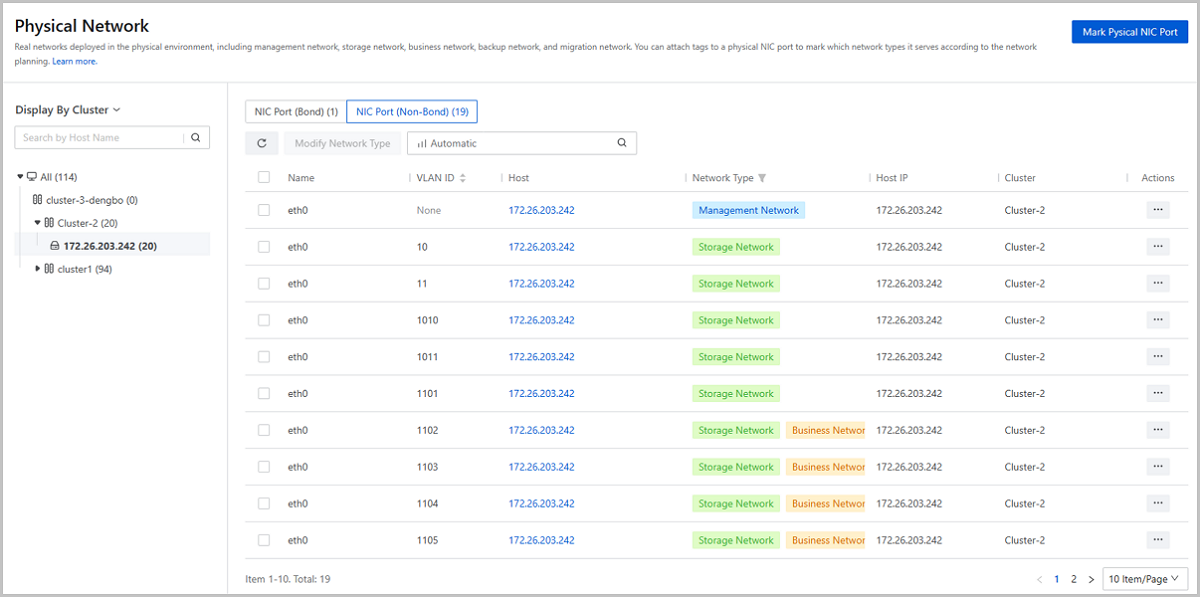
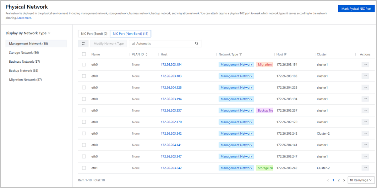
Mark NIC Port with Network Type
On the Physical Network page, choose Mark Physical NIC Port. Then, the Mark Physical NIC Port page is displayed. Set the following parameters:
- Marking Method: Select a marking method. Valid
values: Mark in Bulk and Mark Successively.If you choose Mark in Bulk, you can attach uniform network-type tags to multiple NIC ports from multiple hosts at one time. Set the following parameters:
- Host: Select hosts that the NIC ports to be marked belong to. You can select more than one hosts here. Then, click Add Tag Configuration.
- Physical NIC Port: Select the NIC ports
to be marked. You can select more than one port.Note:
- Select NIC ports that exist on each of the hosts you select. For example, to mark eth0, make sure that each of the hosts has a NIC port named eth0.
- NIC ports that have had a network-type tag attached are not available here. To add or delete tags to/from these NIC ports, go to their action lists and click Modify Network Type.
- VLAN ID: Optional. Select a VLAN subnet
port slaving to the physical NIC port. If you select a VLAN ID
here, the network-type tags are attached to the corresponding
subnet port.Note:
- You can select one or more VLAN ID at one time. If you select more than one physical NIC ports before, you can only select VLAN IDs that exist on each of the NIC ports. For example, to select VLAN ID 100, make sure that all physical NIC ports you select have this VLAN ID.
- VLAN subnet ports that have had a network-type tag attached are not available here. To add or delete tags to/from them, go to their action lists and click Modify Network Type.
- If you do not set this parameter, the network-type tags will be attached directly to the physical NIC ports you select before.
- Physical Network Type: Select
network-type tags. You can select more than one tags for a NIC
port.Note: The management network tags are automatically
attached to corresponding NIC ports by the system. You
cannot add/delete a management network tag to/from a NIC
port by yourself.
If you choose Mark Successively, you can mark NIC ports one by on and attach tags to only one NIC port from one host at one time. Click Add Tag Configuration and set the following parameters:- Host: Select the host that the NIC port to be marked belongs to. One tag configuration supports one host.
- Physical NIC Port: Select the NIC port to
be marked. One tag configuration supports one NIC port.Note: NIC
ports that have had a network-type tag attached are not
available here. To add/delete tags to/from these NIC ports,
go to their action lists and click Modify Network
Type.
- VLAN ID: Optional. Select a VLAN subnet
port slaving to the NIC port. The network-type tags are attached
to these subnet port only. You can select one or more VLAN ID at
one time.Note:
- VLAN subnet ports that have had a network-type tags attached are not available here. To add/delete tags to/from these ports, go to their action lists and click Modify Network Type.
- If you do not set these parameter, the network-type tags will be attached to the physical NIC port you select before by default.
- Physical Network Type: Select
network-type tags. You can select more than one tags for a NIC
port.Note: The management network tags are automatically
attached to corresponding NIC ports by the system. You
cannot add/delete a management network tag to/from a NIC
port by yourself.
After you finish a tag configuration, you can click Add Tag Configuration to mark next NIC port(s).
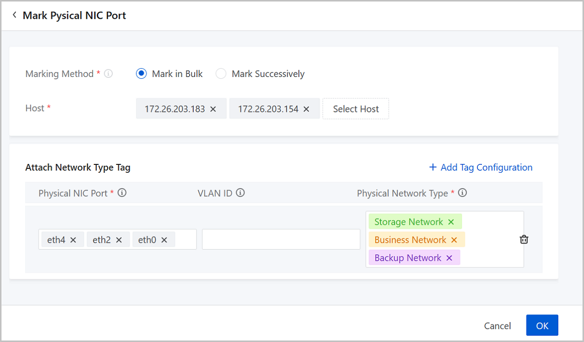
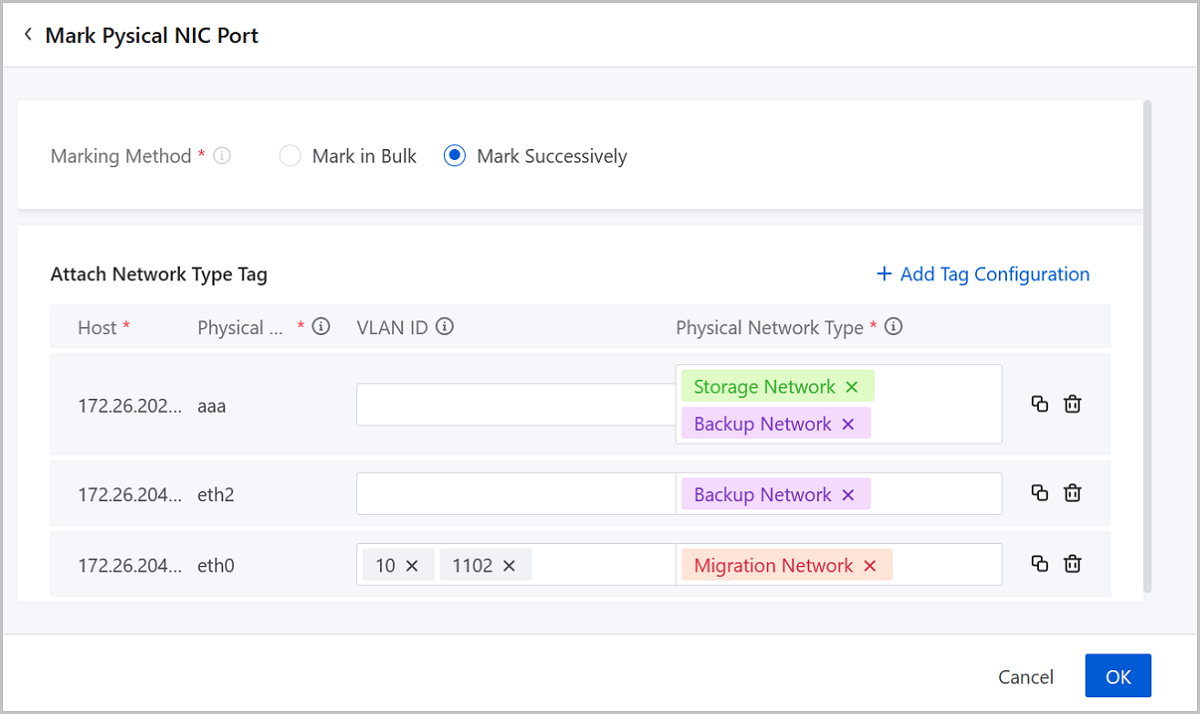
Modify Network Type of NIC Port
Note:
- The management network tags are automatically attached to corresponding NIC ports by the system. You cannot add/delete a management network tag to/from a NIC port by yourself.
- You can add other tags to a NIC port even though it has been marked as management network by the system.
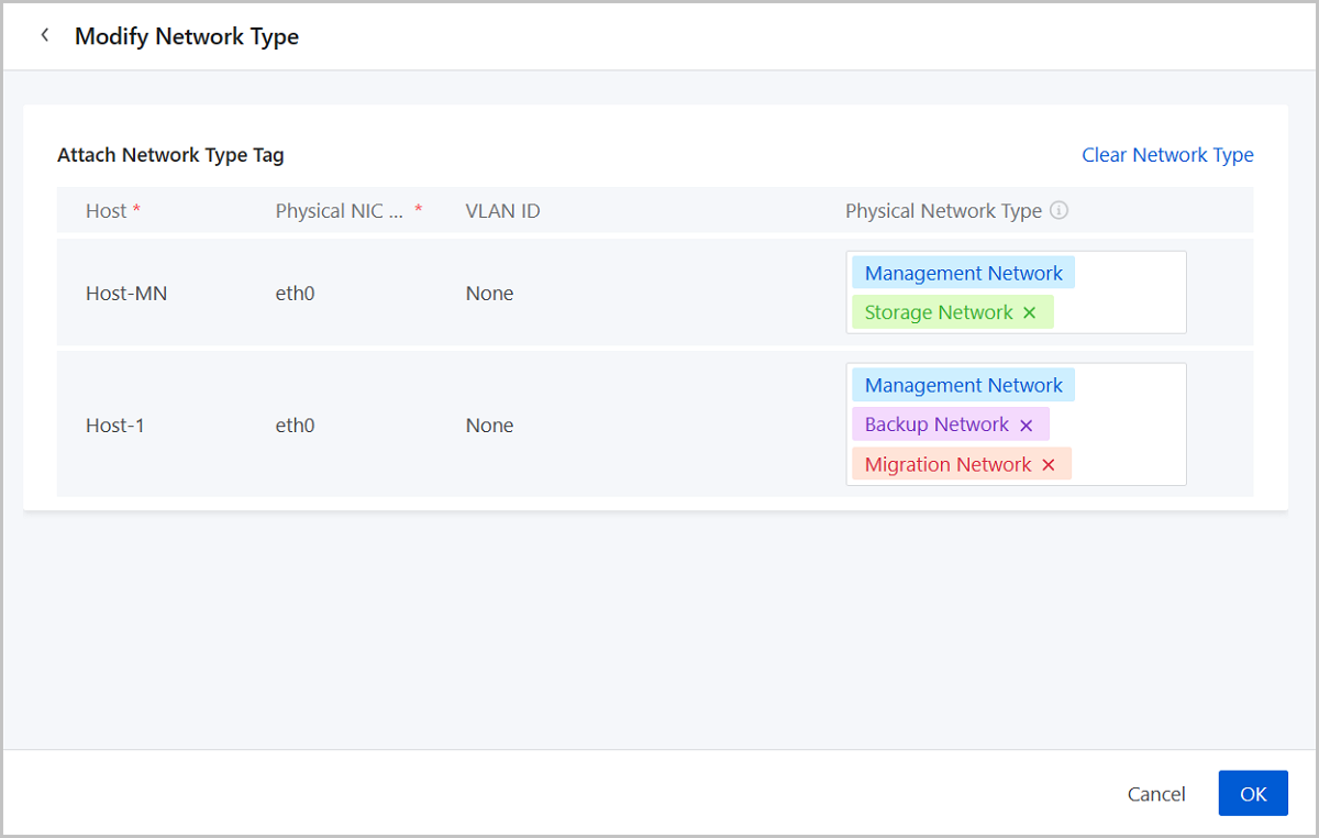
Manage Network Type
Note:
- Custom network type names must not duplicate existing network type names.
- Custom network type names can contain Chinese characters, letters, digits, and spaces and cannot begin or end with spaces.
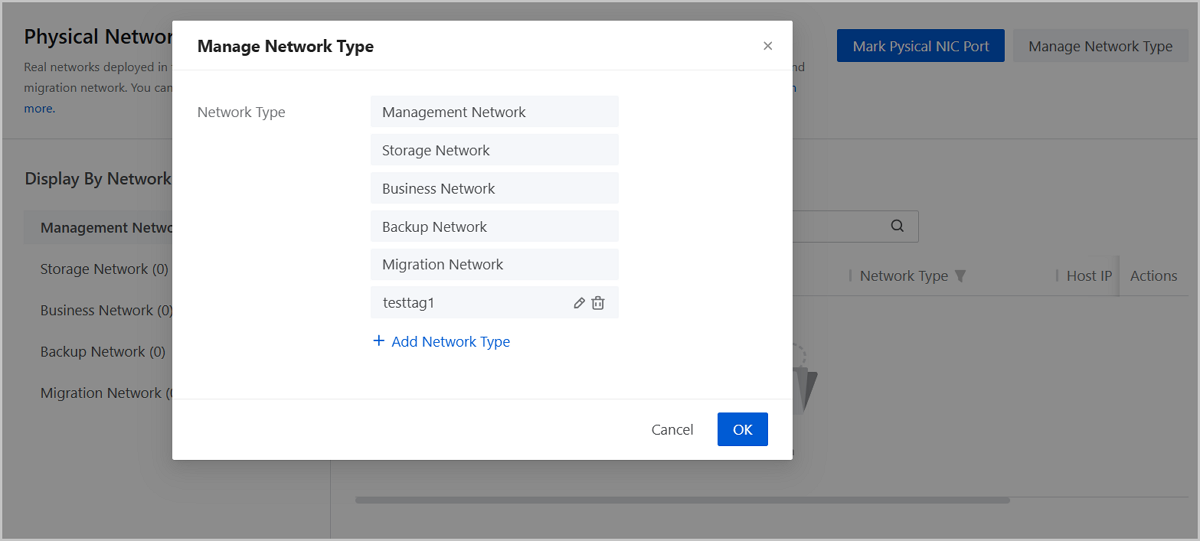
Physical Network Monitoring
ZStack Cloud provides visual monitoring that display physical network flows in graphs. You can view the monitoring on the dashboard, the cluster details page, and the host details page.
Dashboard
Log in to ZStack Cloud, the Dashboard page is displayed. If you have logged in, choose Dashboard on the main menu. On the Dashboard page, locate the monitoring chart Total Host Network IO.
- By default, this chart displays the out/in IO sum of all networks in the zone.
- You can specify one or more network types to make the chart display the IO data only of the networks of the specified type. To ensure the accuracy of the monitoring, we recommend that you attach network-type tags to corresponding NIC ports in advance.
Note: If you do not find the chart Total Host Network IO
on your dashboard, click Customize and add this chart
manually.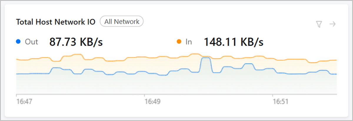
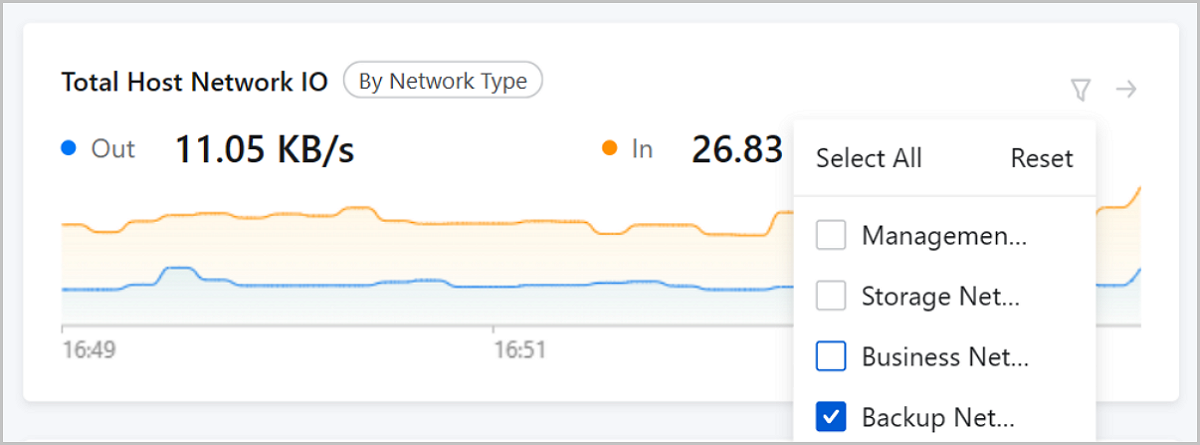
Cluster Details Page
On the main menu of ZStack Cloud, choose . On the Cluster page, click a cluster name and enter its details page. On the cluster details page, locate the monitoring chart NIC Out/In Sum.
- By default, the chart displays the rate sum of all host NICs.
- You can specify one or more network types to make the chart displays the rate sum only of the NICs that belong to the networks of the specified types. To ensure the accuracy of the monitoring, we recommend that you attach network-type tags to corresponding NIC ports in advance.
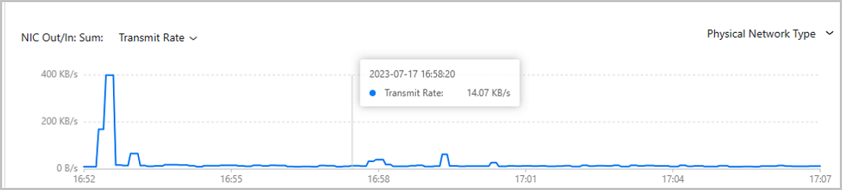
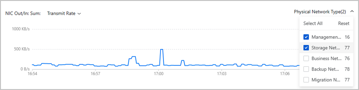
Host Details Page
On the main menu of ZStack Cloud, choose . On the Host page, click a host name and enter its details page. On the host details page, locate the monitoring chart NIC.
- You can specify one or more network types to make the chart display the monitoring data only of the NIC ports that belong to the networks of the specified types. To ensure the accuracy of the monitoring, we recommend that you attach network-type tags to corresponding NIC ports in advance.
- You can specify one or more NICs to make the chart display the monitoring data only of the specified NICs.